


If you already use Amazon Echo or Echo Dot at home or in your office, you can easily add your own devices. In this quick project, we will demonstrate how to control NeoPixels or relays using ESP8266 feather HUZZAH.
You can easily tune your code to easily add as many devices to any feather as you need for any interactive home automation project!
STEP 1 Hardware Required
| Part Description | Amazon.com |
| Amazon Alexa Device | Amazon Echo Dot |
| NodeMCU Development Board | NodeMCU V1.0 |
| 1 or More-Channel Relay Board | SainSmart 4-Channel Relay Module |
| Dupont Style Jumper Wires | Haitronic 120pc Dupont Jumper Wires |
| Bread Board | Qunqi 830 tie point & 400 tie point Breadboard Kit |
STEP 2 Software Required
| Part Description | URL |
| Arduino IDE | Download the latest version of Arduino here |
| NodeMCU Documentation | Visit the NodeMCU project homepage here |
In addition to ESP8266 board support, you should install the following Arduino libraries (search in library manager or manually place folder in Arduino/libraries):
Thanks to this tutorial I learn from here
Easy Alexa (Echo) Control of your ESP8266 Huzzah,
Step 3 Sketch Sheet
STEP 4 Program Microcontroller & Test
PLEASE BE CAREFUL HIGH VOLTAGE
Unplug everything before figuring the wiring with the relay, To control the AC portion of the circuit, I’m using a Power Relay FeatherWing– just interrupt the 220v wire and plug the stripped ends into the Normally Open and Common screw terminals. Remember, if you don’t know AC, find someone who does to supervise.
STEP 5 Upload the Source Code
#include <Arduino.h>
#include <ESP8266WiFi.h>
#include “fauxmoESP.h”
#include “ESPAsyncWebServer.h”
#include <ESPAsyncTCP.h>
#include <Hash.h>
#define WIFI_SSID “WIFI ” // Please Enter Wifi SSID
#define WIFI_PASS “23456789” // Please Enter Wifi Password
#define SERIAL_BAUDRATE 115200
fauxmoESP fauxmo;
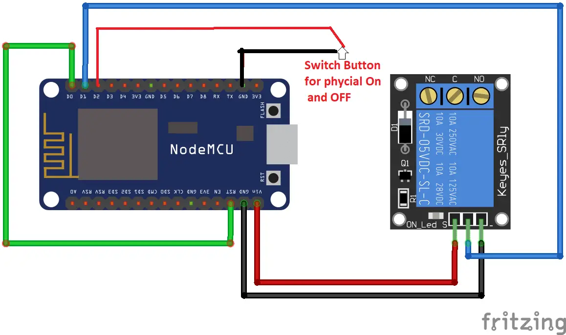
#define RELAY_PIN 5 // PIN D1 For Switch
const int buttonPin = 4; // the pin that the pushbutton is attached to which D2 on board
int buttonState = 0; // current state of the button
int lastButtonState = 0; // previous state of the button
// —————————————————————————–
// Wifi
// —————————————————————————–
void wifiSetup() {
// Set WIFI module to STA mode
WiFi.mode(WIFI_STA);
// Connect
Serial.printf(“[WIFI] Connecting to %s “, WIFI_SSID);
WiFi.begin(WIFI_SSID, WIFI_PASS);
// Wait
while (WiFi.status() != WL_CONNECTED) {
Serial.print(“.”);
delay(100);
}
Serial.println();
// Connected!
Serial.printf(“[WIFI] STATION Mode, SSID: %s, IP address: %s\n”, WiFi.SSID().c_str(), WiFi.localIP().toString().c_str());
}
void callback(uint8_t device_id, const char * device_name, bool state) {
Serial.print(“Device “); Serial.print(device_name);
Serial.print(” state: “);
if (state) {
Serial.println(“ON”);
digitalWrite(RELAY_PIN, HIGH);
} else {
Serial.println(“OFF”);
digitalWrite(RELAY_PIN, LOW);
}
}
void setup() {
pinMode(RELAY_PIN, OUTPUT);
pinMode(buttonPin, INPUT_PULLUP);
digitalWrite(RELAY_PIN, LOW);
// Init serial port and clean garbage
Serial.begin(SERIAL_BAUDRATE);
Serial.println(“FauxMo demo sketch”);
Serial.println(“After connection, ask Alexa/Echo to ‘turn <devicename> on’ or ‘off'”);
// Wifi
wifiSetup();
// Fauxmo
fauxmo.addDevice(“the light”);
fauxmo.onMessage(callback);
}
void loop() {
fauxmo.handle();
// read the pushbutton input pin:
buttonState = digitalRead(buttonPin);
// compare the buttonState to its previous state
if (buttonState != lastButtonState) {
// if the state has changed, increment the counter
if (buttonState == LOW) {
Serial.println(“on”);
digitalWrite(RELAY_PIN, HIGH);
}
else {
// if the current state is LOW then the button
// went from on to off:
Serial.println(“off”);
digitalWrite(RELAY_PIN, LOW);
}
// Delay a little bit to avoid bouncing
delay(50);
}
// save the current state as the last state,
//for next time through the loop
lastButtonState = buttonState;
}
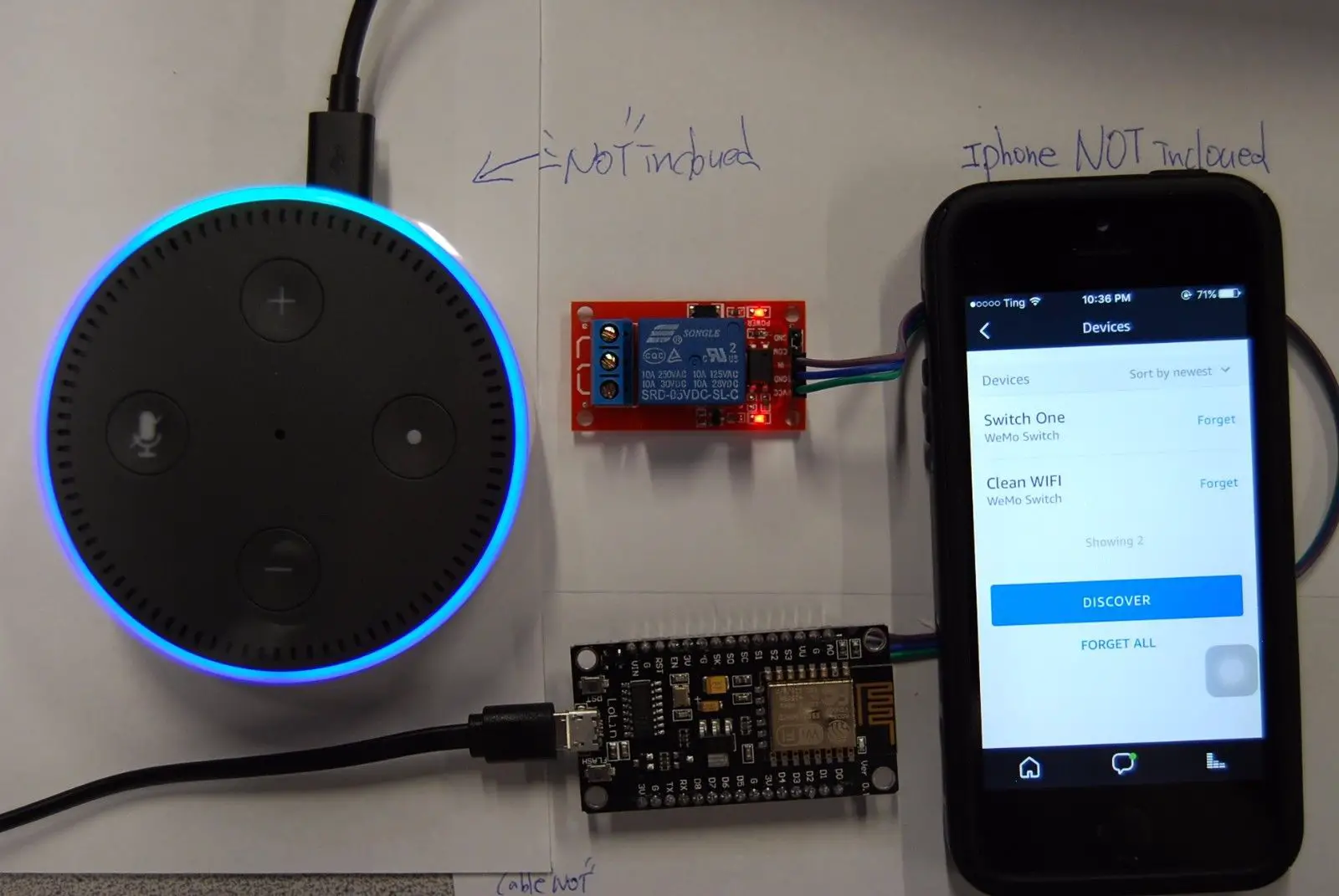
Play!
Tell your Alexa for discover my device after uploading the code and it will detect your smart home device as in ESP8266, and Play with saying Alexa(Computer Or Echo ) Turn On/ Off light.
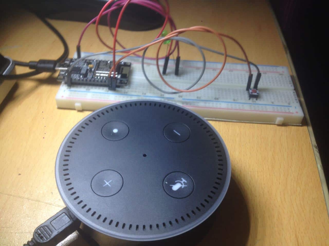
Above is the test video of it I used LED instead of Relay.
You may also like to read this
How to make Alexa Assistant with Raspberry pi 3 Model B
How to setup Torrent in Raspberry Pi/Build Torrent Box


