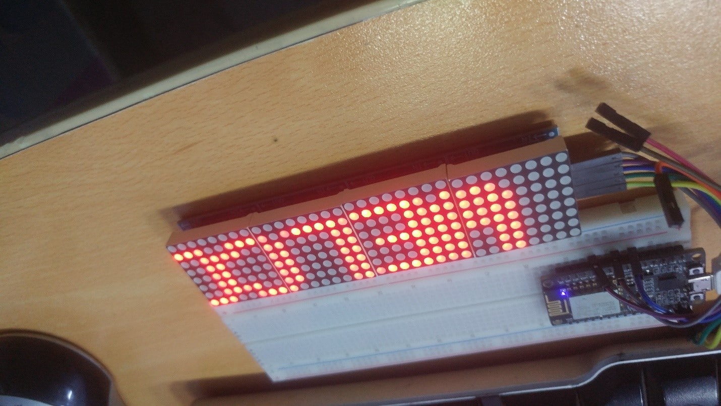


The MAX7219 8-bit LED display module is one of the most popular and widely used display modules and has been used in many 8/16/32-bit MCU projects. It is time to see it working in the ESP8266 CBDBv2 EVO ecosystem. The MAX7219 is a compact serial input/output common cathode.
The display driver connects the microprocessor (μP) to a 7-segment digital LED display with up to 8 digits, a bar graph displays or 64 individual LEDs. On-chip includes BCD code B decoder, multi-channel scanning circuit, segment and digital drivers, and 8×8 static RAM for storing each digit. A segmentation current can be set for all LEDs with an external resistor.
A convenient 4-wire serial interface connects all common μPs. Individual numbers can be addressed and updated without overwriting the entire display. The MAX7219 also allows the user to select either code B decoding or no decoding for each number.
These devices include a 150μA low-power shutdown mode, analog and digital brightness control, a scan limit register that allows the user to display 1 to 8 digits, and a test mode that forces all LEDs to illuminate. This is a 5V operating device. If you need to run it in a 3.3V logic level book, you will A level shifter is required.
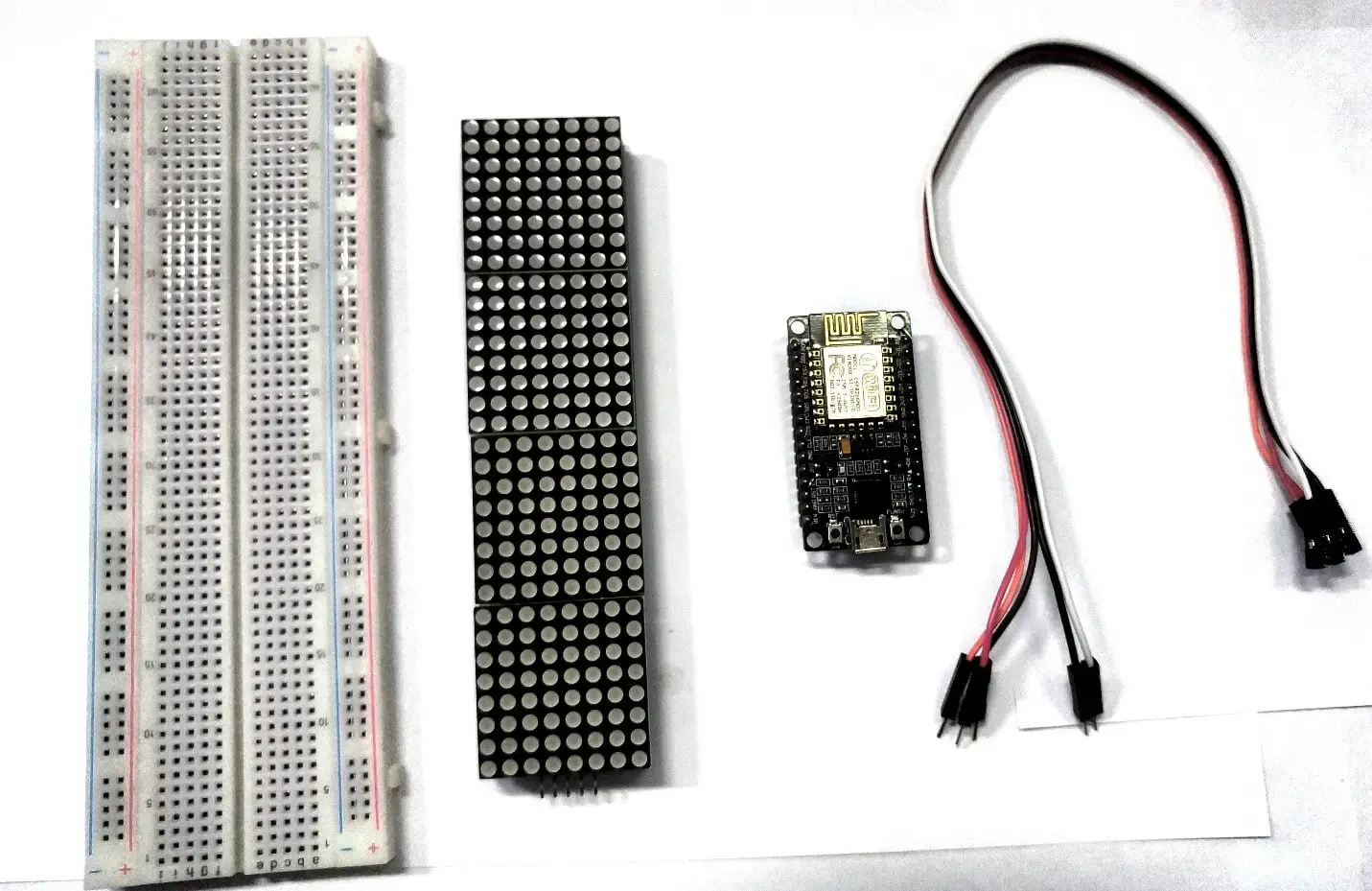
Collect the hardware
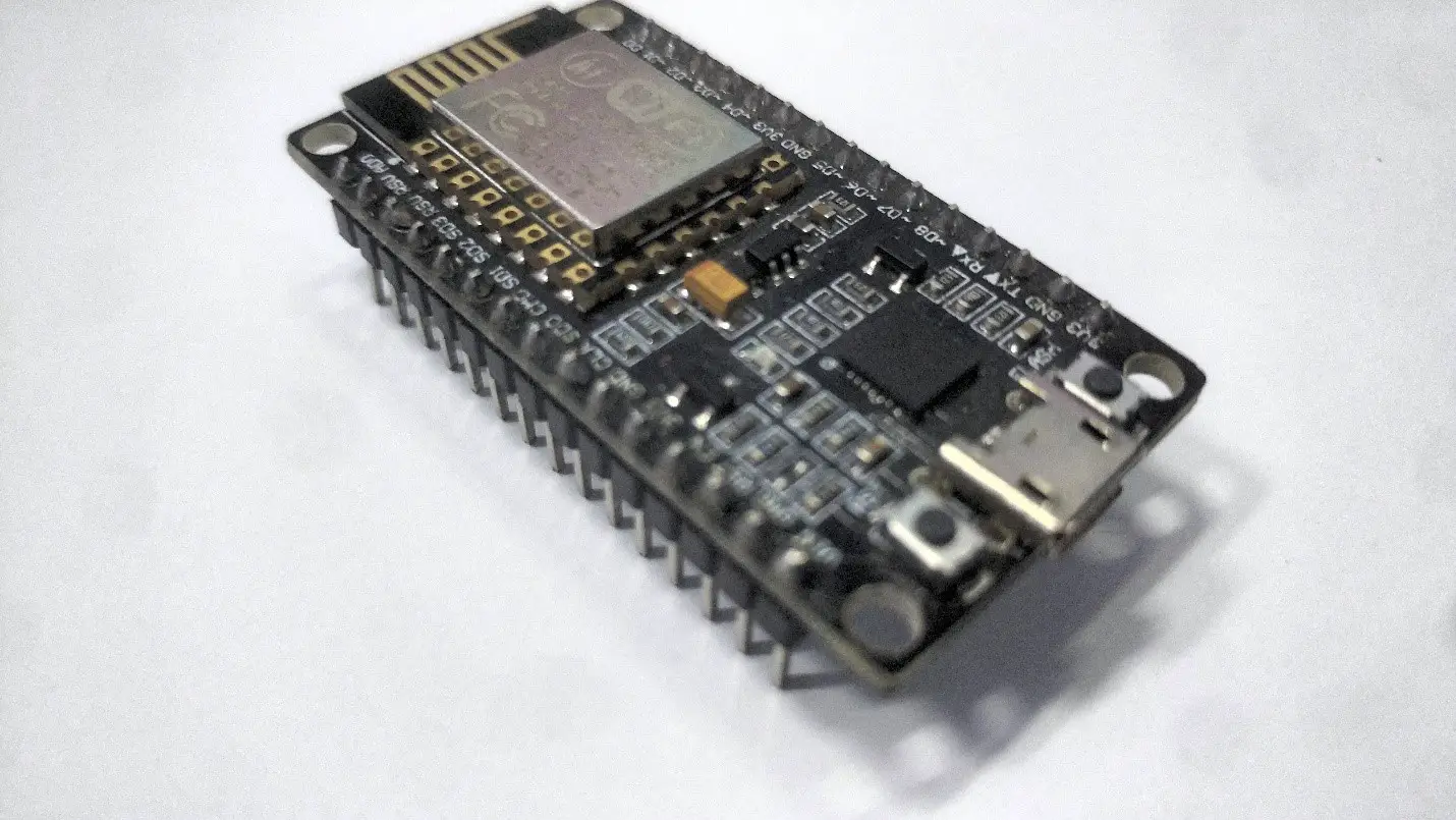
- Esp8266 node mcu View on Amazon
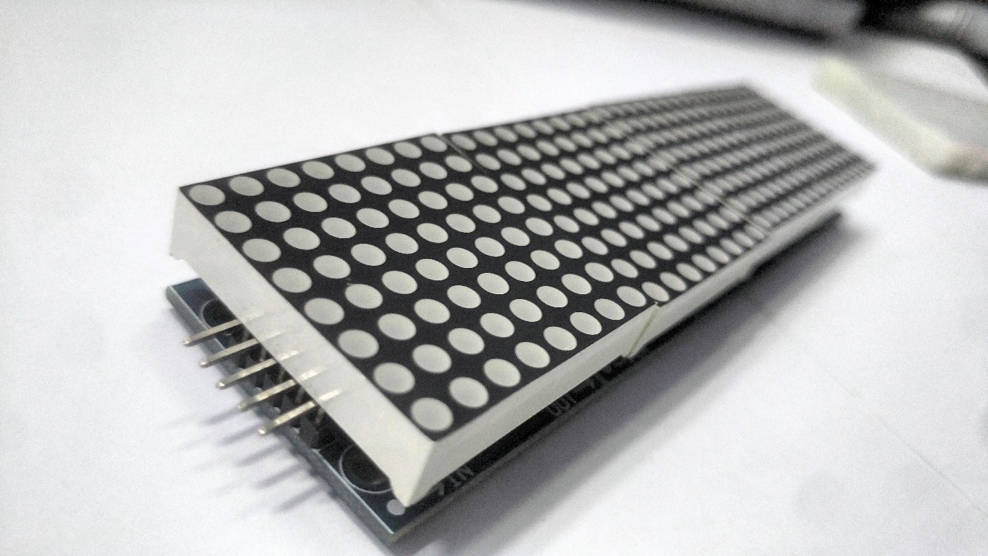
- Dot-matrix with Max7219 controller View on Amazon
- Jumper wires View on Amazon
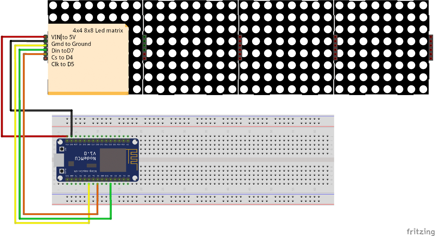
Make the wiring
Wire up the everything as mention below
Note:- I have written a post for people looking for the Best Wireless Access Point to buy?, do read it If you are interested.
Upload source
//– MAX7219 registers
MAXREG_DECODEMODE = 0x09
MAXREG_INTENSITY = 0x0a
MAXREG_SCANLIMIT = 0x0b
MAXREG_SHUTDOWN = 0x0c
MAXREG_DISPTEST = 0x0f
DIN = 7 — 13 – data in pin
CS = 6 — 12 – load (CS) pin
CLK = 5 — 14 – clock pin
gpio.mode(DIN,gpio.OUTPUT)
gpio.mode(CS,gpio.OUTPUT)
gpio.mode(CLK,gpio.OUTPUT)
//2. Write serialised data
function wrByte(data)
i=8
while (i>0)
do
mask = bit.lshift(0x01,i-1)
–print(mask)
gpio.write( CLK, 0) — tick
dser = bit.band(data,mask)
if (dser > 0)
then gpio.write(DIN, 1) — send 1
–print(“1”)
else gpio.write(DIN, 0) — send 0
–print(“0”)
end –endif
–print(dser)
gpio.write( CLK, 1) — tick
i=i-1
end –while
end
//3. Set Register
function setReg(reg, value)
gpio.write(CS, 0)
wrByte(reg) — specify register
tmr.delay(10)
wrByte(value) — send data
gpio.write(CS, 0)
–tmr.delay(10)
gpio.write(CS, 1)
end
//4. Convert anf Print integer number in xxxx format
function print_led_int(c)
th = string.format(“%d”,c / 1000)
h = string.format(“%d”,(c-th*1000) / 100)
t = string.format(“%d”, (c-th1000-h100) / 10)
u = string.format(“%d”, c-th1000-h100-t*10)
–print(string.format(“%d %d %d %d”, th,h,t,u))
setReg(4, th)
setReg(3, h)
setReg(2, t)
setReg(1, u)
end
//5. Create a Display ‘ZERO’ init stage
function zero_all()
v=1
while (v<9) do
setReg(v,0)
v=v+1
end
end
- MAX7219 Initialisation
setReg(MAXREG_SCANLIMIT, 0x07)
tmr.delay(100)
setReg(MAXREG_DECODEMODE, 0xFF) — full decode mode BCD
tmr.delay(100)
setReg(MAXREG_SHUTDOWN, 0x01) — not in shutdown mode
tmr.delay(100)
setReg(MAXREG_DISPTEST, 0x00) — no display test
tmr.delay(100)
setReg(MAXREG_INTENSITY, 0x00) — set Brightness
zero_all() — set all to ZERO
//7. Test Display – 9999 counter
count=0
tmr.alarm(0,1000,1,
function()
count=count+1;
–print(count);
print_led_int(count)
if (count>9999) then count=0;zero_all()
end
end)
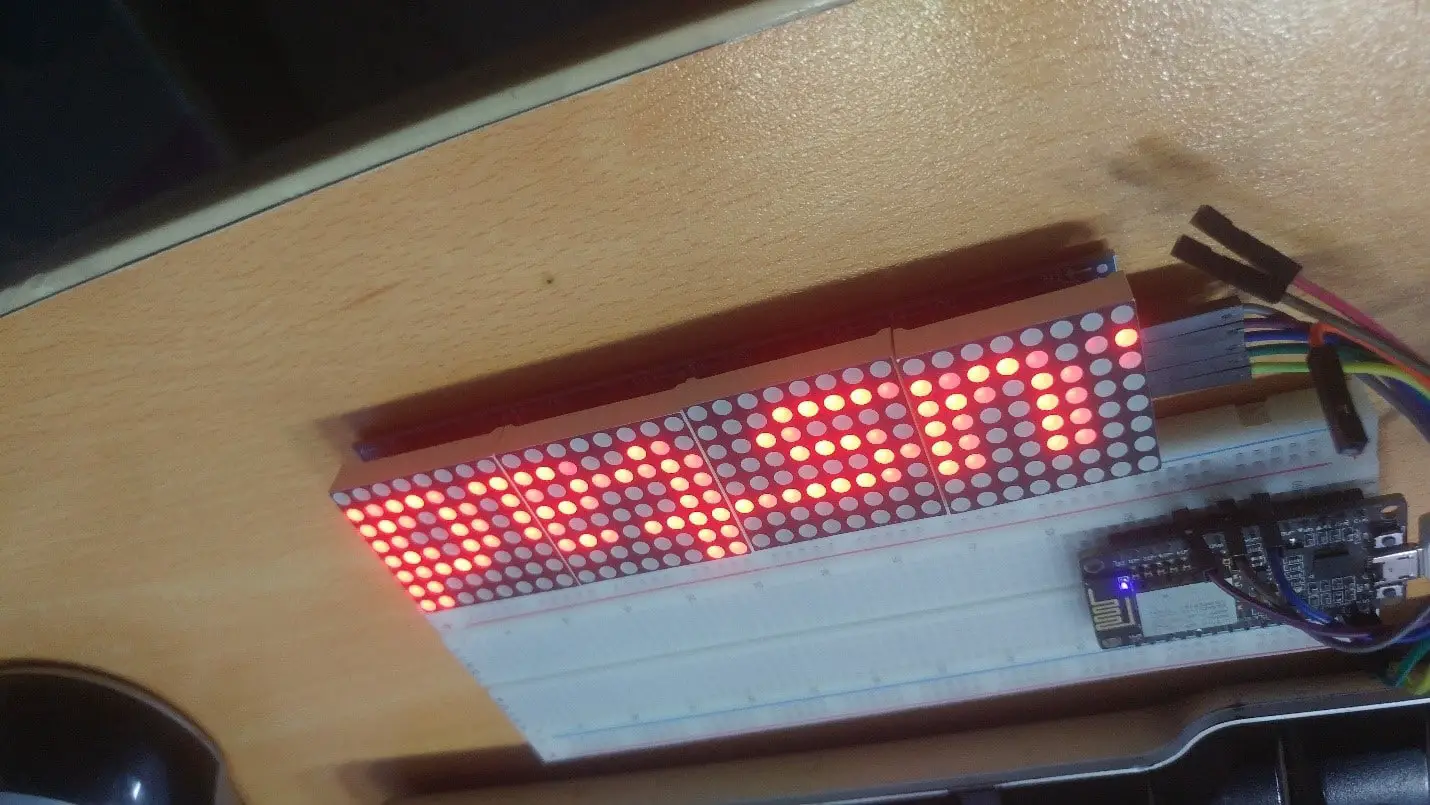
TESTING
After the uploading it will prompt in the browser and start displaying this html file which is mention below
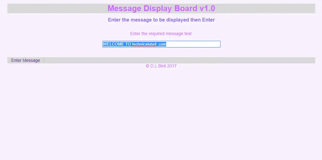
When you click on the Enter Message it will start displaying the Text on the Dot matrix