


When you use the compass app on your smartphone, it will somehow know where the phone is pointing. With the Stargazing app, it can somehow know the sky for which you want to display the constellation correctly. Smartphones and other mobile technologies recognize their direction by using an accelerator, a small device made up of shaft-based motions
When you use the compass app on your smartphone, it will somehow know where the phone is pointing. With the Stargazing app, it can somehow know the sky for which you want to display the constellation correctly. Smartphones and other mobile technologies recognize their direction by using an accelerator, a small device made up of shaft-based motions
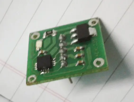
What is ADXL335?
ADXL335 is a small, thin, low power, complete 3-axis accelerometer with signal conditioning voltage output. The product measuring acceleration minimum range of ± 3 g. It measures static gravitational acceleration in tilt sensing applications as well as dynamic acceleration caused by motion, shock or vibration.
The ADXL335 is a 3v3-compatible device that operates from a 3.3v supply and generates a 3.3v peak output. Each axis has three outputs, X, Y, and Z. These are analog outputs and therefore require an ADC in a microcontroller. Arduino solved the problem. We will use Arduino’s simulation capabilities.
Collect Requirements
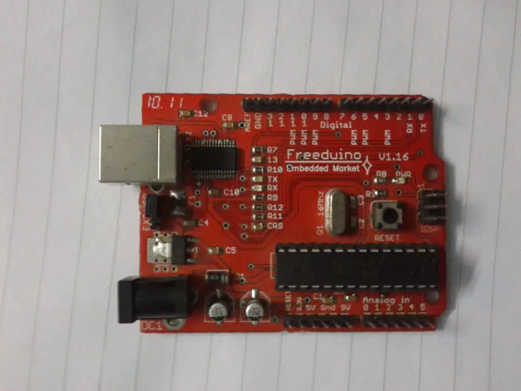
- Arduino – Any Arduino / clone is fine, but I’ve used Freeduino v1.16 (Buy Now)
- ADXL335 accelerometer (Buy Now)
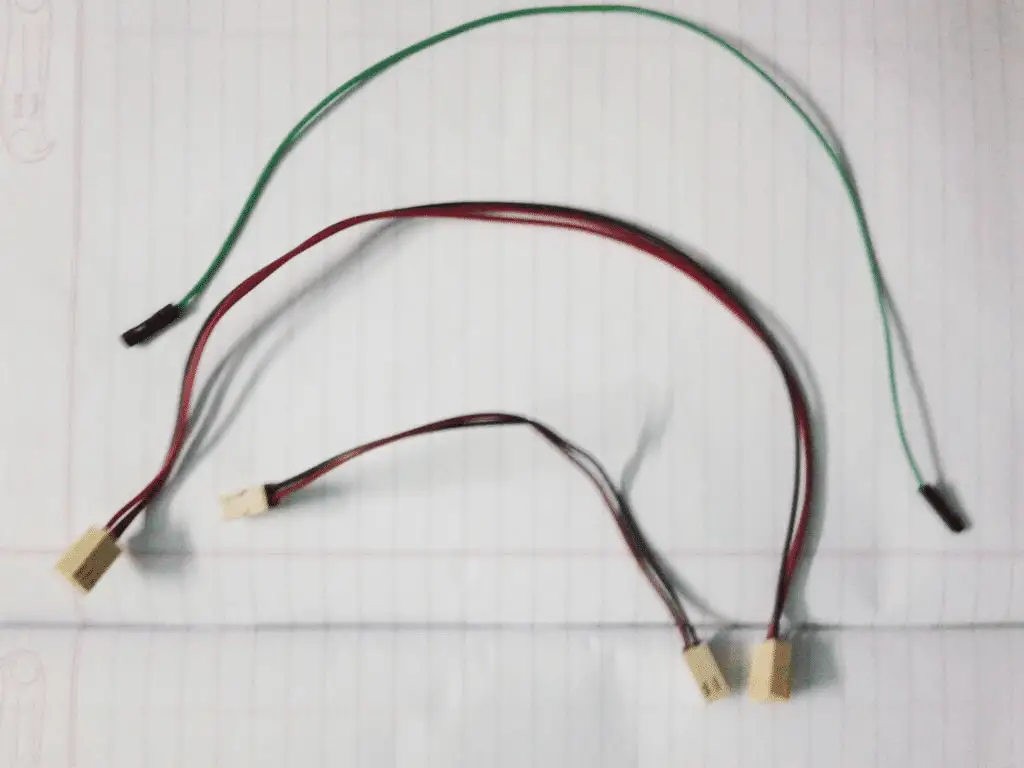
- Connecting wires
- USB cable for connecting the Arduino and your laptop
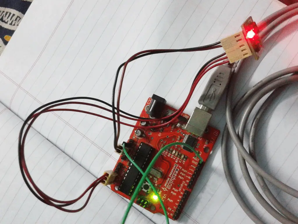
Set up Wiring
The accelerometer module has 5 pins, ie
- GND – GND connected to the Arduino
- VCC – 5V connected to the Arduino
- X – Connect to analog pin A5
- Y- Connect to analog pin A4
- Z- connected to analog pin A3
Note: We do not need to power the module from 3.3v because it already has a 5v to 3.3v converter.
- Use 2-pin replicate to connect Vcc and GND.
- Use the 3-pin reconnect to connect the X, Y, and Z outputs.
- Also connect the AREF pin to 3.3v. This is done to set the reference voltage to 3.3v as the output of the ADXL335 is 3.3v compatible.
Upload Source Code
Note: if you are beginner in Arduino then please have a look at my previous article “Beginner guide for Arduino”
// Connect 3.3v to AREF
const int ap1 = A5;
const int ap2 = A4;
const int ap3 = A3;
int sv1 = 0;
int ov1 = 0;
int sv2 = 0;
int ov2 = 0;
int sv3 = 0;
int ov3 = 0;
void setup () {
// Initialize serial communication at 9600 bps:
Serial.begin (9600);
}
void loop () {
AnalogReference (external); // Connect 3.3v to AREF
// read analog value:
Sv1 = analogRead (ap1);
// Map it to the range of analog output:
Ov1 = map (sv1,0,1023,0,255);
// Change the analog output value:
Delay (2);
//
Sv2 = analogRead (ap2);
Ov2 = map (sv2,0,1023,0,255);
//
Delay (2);
//
Sv3 = analogRead (ap3);
Ov3 = map (sv3,0,1023,0,255);
// print the result to the serial monitor:
Serial.print (“Xsensor1 =”);
Serial.print (SV1);
Serial.print (“\ t output1 =”);
Serial.println (OV1);
Serial.print (“Ysensor2 =”);
Serial.print (SV2);
Serial.print (“\ t output2 =”);
Serial.println (OV2);
Serial.print (“Zsensor3 =”);
Serial.print (SV3);
Serial.print (“\ t output3 =”);
Serial.println (OV3);
Delay (3000);
}
We will show two different values for an analog value read. The first value is the ADC conversion value at 10-bit resolution (0 to 1023) and the second value is PWM-mapped and is 8-bit resolution (0 to 255).
The three values of the X, Y and Z axes are repeated after a 3-second interval.