


In this tutorial, I will show you how an accelerometer/gyroscope works with an Arduino UNO. In particular, I will use the MPU-6050 sensor.
The MPU-6050 sensor contains, in a single integrated, a 3-axis MEMS accelerometer and a 3-axis MEMS gyroscope. With the gyroscope, we can measure the angular acceleration of a body on its own axis, while with the accelerometer we can measure the acceleration of a body along one direction. It is very precise, as it has a 16-bit AD (from analog to digital) converter for each channel. Therefore, it captures the x, y and z channels at the same time. The sensor has a standard I²C communication protocol, so it is easy to interface with the Arduino world.
The MPU-6050 sensor is not even expensive, perhaps it is the cheapest on the market, especially considering the fact that it combines an accelerometer and a gyroscope.
Here are some features of the MPU-6050 sensor:-
- Chip with integrated 16-bit AD converter
- Gyroscope measuring range: ± 250, 500, 1000 and 2000 ° / s
- Accelerometer measuring range: +2, +4, +8, +16 g
- Interface: I²C
- Power supply: from 3V to 5V
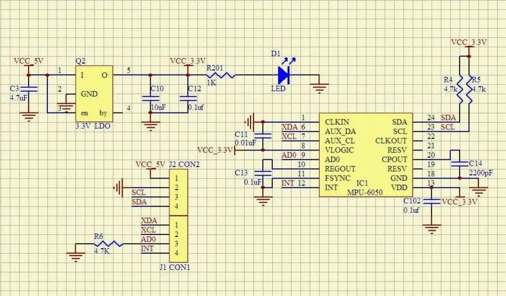
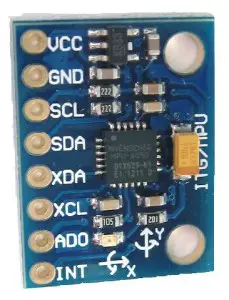
For my test, I purchased a GY-521 module so that the MPU-6050 sensor is ready for use. Here is the wiring diagram of the GY-521 module for those who want to build it themselves:-
Now let’s move on to the actual tutorial by going to see how to use this module with an Arduino Uno.
List of material:
SCHEME
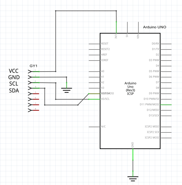
Connections for Arduino Uno:
GY-521 Arduino Uno
VCC 3.3V
GNS GND
SCL A5
SDA A4
The scheme and the links are addressed only for Arduino Uno, but the tutorial is also valid for all the other Arduino boards. The only thing that changes in the connections are the 2 pins I2C, that is SDA and SCL (Ex. On Arduino Uno the SCL pin is on the A5 pin while on Arduino Mega it is on pin 20). Just consult the datasheet or do some research on google to find the I2C inputs of your board.
Now let’s move on to the verification sketch, in this way we will verify if our module GY-521 is connected correctly to Arduino.
#include <Wire.h>
void setup()
{
Wire.begin();
Serial.begin(9600);
Serial.println(“\nI2C Scanner”);
}
void loop()
{
byte error, address;
int nDevices;
Serial.println(“Scanning…”);
nDevices = 0;
for(address = 1; address < 127; address++ )
{
// The i2c_scanner uses the return value of
// the Write.endTransmisstion to see if
// a device did acknowledge to the address.
Wire.beginTransmission(address);
error = Wire.endTransmission();
if (error == 0)
{
Serial.print(“I2C device found at address 0x”);
if (address<16)
Serial.print(“0”);
Serial.print(address,HEX);
Serial.println(” !”);
nDevices++;
}
else if (error==4)
{
Serial.print(“Unknow error at address 0x”);
if (address<16)
Serial.print(“0”);
Serial.println(address,HEX);
}
}
if (nDevices == 0)
Serial.println(“No I2C devices found\n”);
else
Serial.println(“done\n”);
delay(5000); // wait 5 seconds for next scan
}
After loading the sketch on Arduino, open the Serial Monitor.
If this message comes out:
You have done everything right so far
Good! If you have done the check and everything went well we just have to continue the tutorial and try the features of the MPU-6050 sensor, ie reading the 3 axes (X, Y, Z) of the gyroscope, of the accelerometer and to finish also the temperature measurement in degrees Celsius (° C).
First of all you have to load this sketch on the Arduino board:
// MPU-6050 Short Example Sketch
#include<Wire.h>
const int MPU=0x68; // I2C address of the MPU-6050
int16_t AcX,AcY,AcZ,Tmp,GyX,GyY,GyZ;
void setup(){
Wire.begin();
Wire.beginTransmission(MPU);
Wire.write(0x6B); // PWR_MGMT_1 register
Wire.write(0); // set to zero (wakes up the MPU-6050)
Wire.endTransmission(true);
Serial.begin(9600);
}
void loop(){
Wire.beginTransmission(MPU);
Wire.write(0x3B); // starting with register 0x3B (ACCEL_XOUT_H)
Wire.endTransmission(false);
Wire.requestFrom(MPU,14,true); // request a total of 14 registers
AcX=Wire.read()<<8|Wire.read(); // 0x3B (ACCEL_XOUT_H) & 0x3C (ACCEL_XOUT_L)
AcY=Wire.read()<<8|Wire.read(); // 0x3D (ACCEL_YOUT_H) & 0x3E (ACCEL_YOUT_L)
AcZ=Wire.read()<<8|Wire.read(); // 0x3F (ACCEL_ZOUT_H) & 0x40 (ACCEL_ZOUT_L)
Tmp=Wire.read()<<8|Wire.read(); // 0x41 (TEMP_OUT_H) & 0x42 (TEMP_OUT_L)
GyX=Wire.read()<<8|Wire.read(); // 0x43 (GYRO_XOUT_H) & 0x44 (GYRO_XOUT_L)
GyY=Wire.read()<<8|Wire.read(); // 0x45 (GYRO_YOUT_H) & 0x46 (GYRO_YOUT_L)
GyZ=Wire.read()<<8|Wire.read(); // 0x47 (GYRO_ZOUT_H) & 0x48 (GYRO_ZOUT_L)
Serial.print(“Accelerometer: “);
Serial.print(“X = “); Serial.print(AcX);
Serial.print(” | Y = “); Serial.print(AcY);
Serial.print(” | Z = “); Serial.println(AcZ);
//equation for temperature in degrees C from datasheet
Serial.print(“Temperature: “); Serial.print(Tmp/340.00+36.53); Serial.println(” C “);
Serial.print(“Gyroscope: “);
Serial.print(“X = “); Serial.print(GyX);
Serial.print(” | Y = “); Serial.print(GyY);
Serial.print(” | Z = “); Serial.println(GyZ);
Serial.println(” “);
delay(333);
}
After opening the Serial Monitor you should see the values of the X, Y, Z axis of the accelerometer, gyroscope and the temperature in ° C as in the following picture:
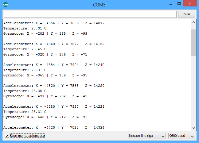
This last sketch is quite simple to understand, especially if you have a good programming base and a bit of experience with Arduino. On the variables AcX, AcY, AcZ = accelerometer; Tmp = temperature; GyX, GyY, GyZ = gyroscope; the values of the X, Y, Z axes are stored. In this way you can manage these values as you want, as I will show you soon.
PROJECT: MANAGEMENT OF TWO SERVOMOTORS USING A GY-521 MODULE
This project will be a practical example to make you understand how easy it is to interface the GY-521 module with Arduino. I will use only the values of the accelerometer axes and calculate the Pitch and Roll angles (as described in my tutorial) to rotate the two servomotors from 0 ° to 179 ° according to the position of the accelerometer. Before proceeding I suggest you watch the following video to better understand what I’m talking about.

You may also like to read these articles
How to Build Rain Detector Using Arduino
Build Distance Measuring System with Arduino UNO and Ultrasonic sensor HC-Sr04


