


In this RFID-based time and attendance system project, we will explain to you how to use RFID card to authorize and statistic attendance automatically. RFID technology (radio frequency identification and detection) is commonly used in schools, colleges, offices, and stations for a variety of purposes to automatically track people. Here, we will count the attendance of authorized personnel by using RFID.
- Raspberry Pi (with bootable SD card) Buy Here
- Button
- Buzzer Buy Here
- 16×2 character LCD Buy Here
- 10K resistor Buy Here
- LED Lights
- 1k resistor Buy Here
- Breadboard Buy Here
- RFID reader Buy Here
- Jumper Wires
What are RFID and Tags card?
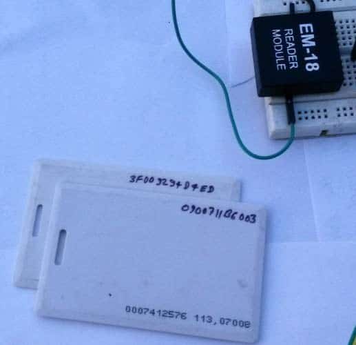
RFID is an electronic device that has two parts – one an RFID reader and the other a RFID tag or card. When we put the RFID tag close to the RFID reader, it reads the tag data in sequence. RFID tags have 12-digit alphanumeric codes in the coil. The RFID baud rate is 9600 bps. RFID uses electromagnets to transfer data from the reader to the tag or tag to the reader.
Project working
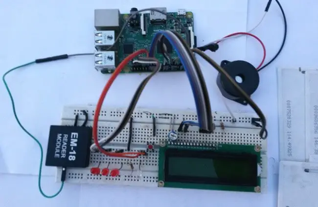
Here Raspberry Pi 3 controls the entire process of this project (the user can use any Raspberry Pi Board). The RFID reader reads the ID of the RFID card, which is received via the UART, then the RPi verifies the card and displays the result on the LCD screen.
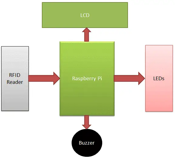
When a person scans their RFID tag near an RFID reader, the RFID reads the tag’s data and sends it to the Raspberry Pi. The Raspberry Pi then reads the unique identification number of the RFID tag and then compares the data with predefined data or information. If the data matches the predefined data, the Raspberry Pi adds 1 to the attendance of the tagged person, and if the match does not match, the microcontroller displays an “invalid card” message on the LCD and the buzzer beeps for a while. Here, we also added a button to see the total number. Attendance of all students. Here we use four RFID tags, three of which are used to record the attendance of three students and one to serve as an invalid card.
Circuit Diagram
The Raspberry Pi Time Attendance System project’s circuit diagram is very simple, including the Raspberry Pi 3, RFID readers, RFID tags, buzzers, LEDs and LCDs. So we have here full control of raspberry pi controls the complete process of reading data from the reader, comparing the data with predefined data and as well driving the buzzer, driving the status LED and sending the status to the LCD display. RFID reader for reading RFID tags. The buzzer is used to indicate and is driven by the built-in NPN transistor. LCD is used to display status or message.
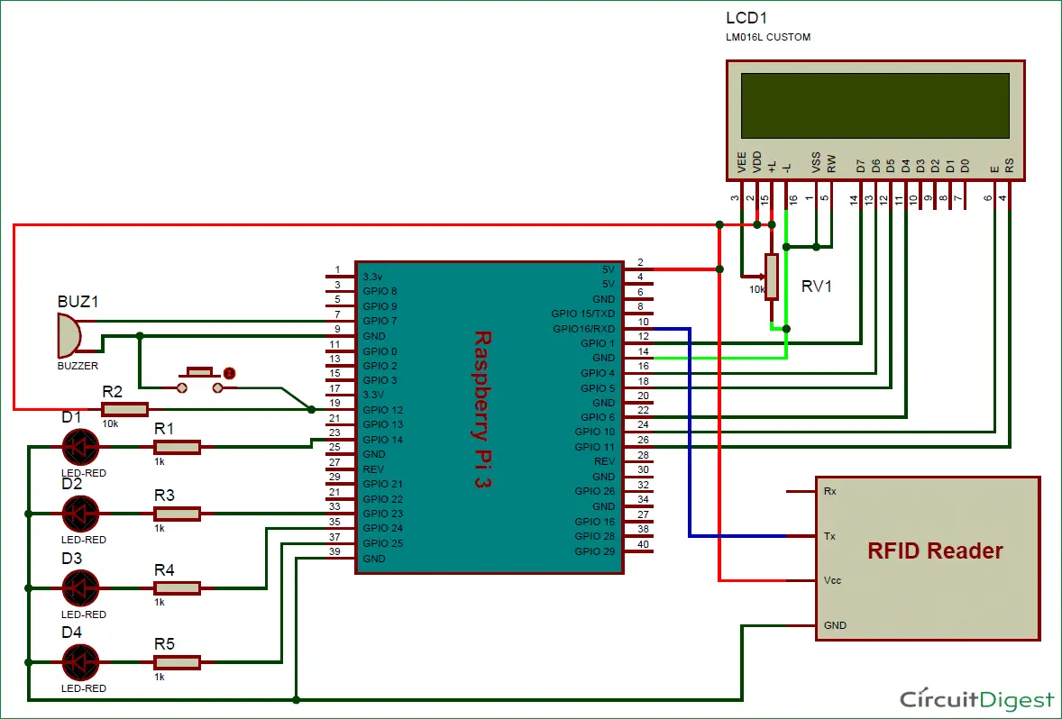
The connection is easy. The LCD is connected to the Raspberry Pi in 4-bit mode. The RS, RW and EN pins of the LCD are directly connected to wiringPi GPIO 11, gnd and 10. Data pins are connected to wiringPi GPIOs 6, 5, 4 and 1. A 10K capacitor is used to set the contrast or brightness of the LCD. The buzzer is connected to ground via wiringPi GPIO pin 7. Use the appropriate RFID card to connect the three LEDs for student instruction. An LED is used to indicate that the system is ready to scan the RFID card. wiringPi GPIO pin 12 also has a button connected to display attendance counts. The RFID reader is connected to the UART pin (wired GPIO pin 16).
Installation of Wiring library
As in Python, we imported and imported RPi.GPIO as an IO header file to use the GPIO pins of the Raspberry Pi. In C, we needed to use the wiringPi library to use the GPIO pins in the C program. We can install it one by one using the command below, which you can run from a terminal or an SSH client like Putty if you are using Windows.
sudo apt-get install git-core
sudo apt-get update
sudo apt-get upgrade
git clone git://git.drogon.net/wiringPi
cd wiringPi
git pull origin
cd wiringPi
./build
Test the installation of a wiringPi library, use below commands:
gpio -v
gpio readall
Run Python Script
#include<wiringPi.h>
#include <wiringSerial.h>
#include<stdio.h>
#include <string.h>
#define RS 11
#define EN 10
#define D4 6
#define D5 5
#define D6 4
#define D7 1
#define led1 23
#define led2 24
#define led3 25
#define led5 14
#define buzz 7
#define in1 21
int sp ;
int count1=0,count2=0,count3=0;
char ch;
char rfid[13];
int i=0;
char temp[5];
void check_button();
void lcdcmd(unsigned int ch)
{
int temp=0x80;
digitalWrite(D4, temp & ch<<3);
digitalWrite(D5, temp & ch<<2);
digitalWrite(D6, temp & ch<<1);
digitalWrite(D7, temp & ch);
digitalWrite(RS, LOW);
digitalWrite(EN, HIGH);
delay(10);
digitalWrite(EN, LOW);
digitalWrite(D4, temp & ch<<7);
digitalWrite(D5, temp & ch<<6);
digitalWrite(D6, temp & ch<<5);
digitalWrite(D7, temp & ch<<4);
digitalWrite(RS, LOW);
digitalWrite(EN, HIGH);
delay(10);
digitalWrite(EN, LOW);
}
void write(unsigned int ch)
{
int temp=0x80;
digitalWrite(D4, temp & ch<<3);
digitalWrite(D5, temp & ch<<2);
digitalWrite(D6, temp & ch<<1);
digitalWrite(D7, temp & ch);
digitalWrite(RS, HIGH);
digitalWrite(EN, HIGH);
delay(10);
digitalWrite(EN, LOW);
digitalWrite(D4, temp & ch<<7);
digitalWrite(D5, temp & ch<<6);
digitalWrite(D6, temp & ch<<5);
digitalWrite(D7, temp & ch<<4);
digitalWrite(RS, HIGH);
digitalWrite(EN, HIGH);
delay(10);
digitalWrite(EN, LOW);
}
void clear()
{
lcdcmd(0x01);
}
void setCursor(int x, int y)
{
int set=0;
if(y==0)
set=128+x;
if(y==1)
set=192+x;
lcdcmd(set);
}
void print(char *str)
{
while(*str)
{
write(*str);
str++;
}
}
void begin(int x, int y)
{
lcdcmd(0x02);
lcdcmd(0x28);
lcdcmd(0x06);
lcdcmd(0x0e);
lcdcmd(0x01);
}
void buzzer()
{
digitalWrite(buzz, HIGH);
delay(1000);
digitalWrite(buzz, LOW);
}
void wait()
{
digitalWrite(led5, LOW);
delay(3000);
}
void serialbegin(int baud)
{
if ((sp = serialOpen (“/dev/ttyS0”,baud)) < 0)
{
clear();
print(“Unable to open”);
setCursor(0,1);
print(“serial Port”);
}
}
void setup()
{
if (wiringPiSetup () == -1)
{
clear();
print(“Unable to start”);
setCursor(0,1);
print(“wiringPi”);
}
pinMode(led1, OUTPUT);
pinMode(led2, OUTPUT);
pinMode(led3, OUTPUT);
pinMode(led5, OUTPUT);
pinMode(buzz, OUTPUT);
pinMode(RS, OUTPUT);
pinMode(EN, OUTPUT);
pinMode(D4, OUTPUT);
pinMode(D5, OUTPUT);
pinMode(D6, OUTPUT);
pinMode(D7, OUTPUT);
pinMode(in1, INPUT);
digitalWrite(in1, HIGH);
begin(16,2);
serialbegin(9600);
}
void get_card()
{
digitalWrite(led5, HIGH);
i=0;
while(i<12)
{
check_button();
while(serialDataAvail (sp))
{
ch= serialGetchar(sp);
rfid[i]=ch;
fflush (stdout) ;
i++;
}
}
rfid[i]=’\0′;
buzzer();
return;
}
void main()
{
setup();
clear();
print(“Attendance Systm”);
setCursor(0,1);
print(“using RPI “);
delay(2000);
clear();
print(“Circuit Digest”);
setCursor(0,1);
print(“Welcomes you”);
delay(2000);
clear();
print(“System Ready”);
delay(1000);
clear();
while(1)
{
clear();
print(“Place Your Card:”);
get_card();
setCursor(0,1);
print(rfid);
delay(1000);
if(strncmp(rfid,”0900711B6003″,12)==0)
{
count1++;
clear();
print(“Attd. Registered”);
setCursor(0,1);
print(“Student 1″);
digitalWrite(led1, HIGH);
buzzer();
digitalWrite(led1, LOW);
wait();
}
else if(strncmp(rfid,”090070FE6EE9”,12)==0)
{
count2++;
clear();
print(“Attd. Registered”);
setCursor(0,1);
print(“Student 2″);
digitalWrite(led2, HIGH);
buzzer();
digitalWrite(led2, LOW);
wait();
}
else if(strncmp(rfid,”3F0072C049C4”,12)==0)
{
count3++;
clear();
print(“Attd. Registered”);
setCursor(0,1);
print(“Student 3”);
digitalWrite(led3, HIGH);
buzzer();
digitalWrite(led3, LOW);
wait();
}
else
{
clear();
print(“Invalid Card”);
buzzer();
buzzer();
wait();
}
}
}
void check_button()
{
if(digitalRead(in1)==0)
{
digitalWrite(led5, LOW);
clear();
setCursor(0,0);
print(“std1 std2 std3″);
setCursor(1,1);
sprintf(temp,”%d”,count1);
print(temp);
setCursor(7,1);
sprintf(temp,”%d”,count2);
print(temp);
setCursor(13,1);
sprintf(temp,”%d”,count3);
print(temp);
delay(5000);
digitalWrite(led5, HIGH);
clear();
print(“Place Your Card:”);
}
}

You may also like to read these articles


