


In this article I will explain how to build your own multimeter with Arduino Uno and character LCD, I am using a character LCD with i2c communication module of LCD.
Arduino Uno requires 5-volt power to run, then we need at least 7.4 to a 9-volt battery. Since Arduino pins support only up to 5 volts, we need a voltage divider. It consists of two resistors in series.
In order to divide the voltage in half, we need two resistors with the same value. A 1K to 20K resistor can be used, but the larger the resistance, the lower the power dissipation in the voltage divider. I was not good at calculating such things, but this is what I summed up from the information I read. If I’m wrong, you can correct me and the best explanation for the comment section is very welcome.
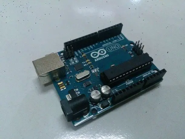
- Arduino Uno or compatible. (Buy Now)
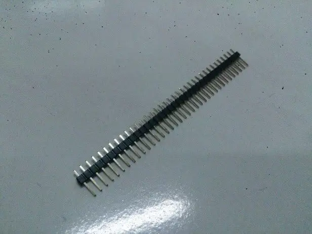
- Male pins (we only need four pins).
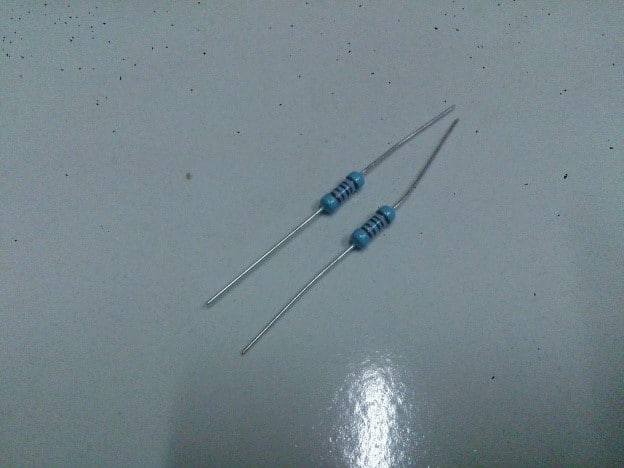
- Two resistors of the same value (here I use 12K).
- Two-pin female connector. The photo shows three pins as it is mine. Here I use the power switch connector to replace the motherboard 🙂
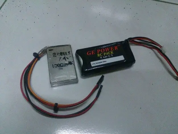
- Battery (I use 7.4V lithium battery).
- 16×2 LCD with I2C adapter. Later, you can switch it to the red LED to indicate that you want the voltage level to be low on the battery. (Buy Now)
- The mini breadboard for the testing phase is optional. (Buy Now)
Arduino code
Well, I would like to upload this sketch to the Arduino first and then connect it to the battery for testing. Uploading the content will not show anything until all of the items needed for this project are connected, but sooner or later you still need to upload the sketch. I’m not sure what happens if you have both USB and Vin powered at the same time. I think this will be fine, Arduino designers must consider this possibility and prevent such conflicts of power. But I’ll never try it on purpose, risking burning my Arduino. 😛
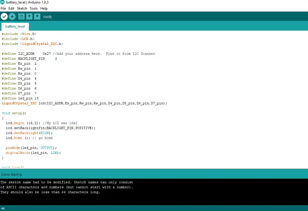
Upload Source Code
#include <Wire.h>
#include <LCD.h>
#include <LiquidCrystal_I2C.h>
#define I2C_ADDR 0x27 //Add your address here. Find it from I2C Scanner
#define BACKLIGHT_PIN 3
#define En_pin 2
#define Rw_pin 1
#define Rs_pin 0
#define D4_pin 4
#define D5_pin 5
#define D6_pin 6
#define D7_pin 7
#define led_pin 13
LiquidCrystal_I2C lcd(I2C_ADDR,En_pin,Rw_pin,Rs_pin,D4_pin,D5_pin,D6_pin,D7_pin);
void setup()
{
lcd.begin (16,2); //My LCD was 16×2
lcd.setBacklightPin(BACKLIGHT_PIN,POSITIVE);
lcd.setBacklight(HIGH);
lcd.home (); // go home
pinMode(led_pin, OUTPUT);
digitalWrite(led_pin, LOW);
}
void loop()
{
printVolts();
}
void printVolts()
{
int sensorValue = analogRead(A0); //read the A0 pin value
float voltage = sensorValue * (5.00 / 1023.00) * 2; //convert the value to a true voltage.
lcd.setCursor(0,0);
lcd.print(“voltage = “);
lcd.print(voltage); //print the voltage to LCD
lcd.print(” V”);
if (voltage < 6.50) //set the voltage considered low battery here
{
digitalWrite(led_pin, HIGH);
}
}
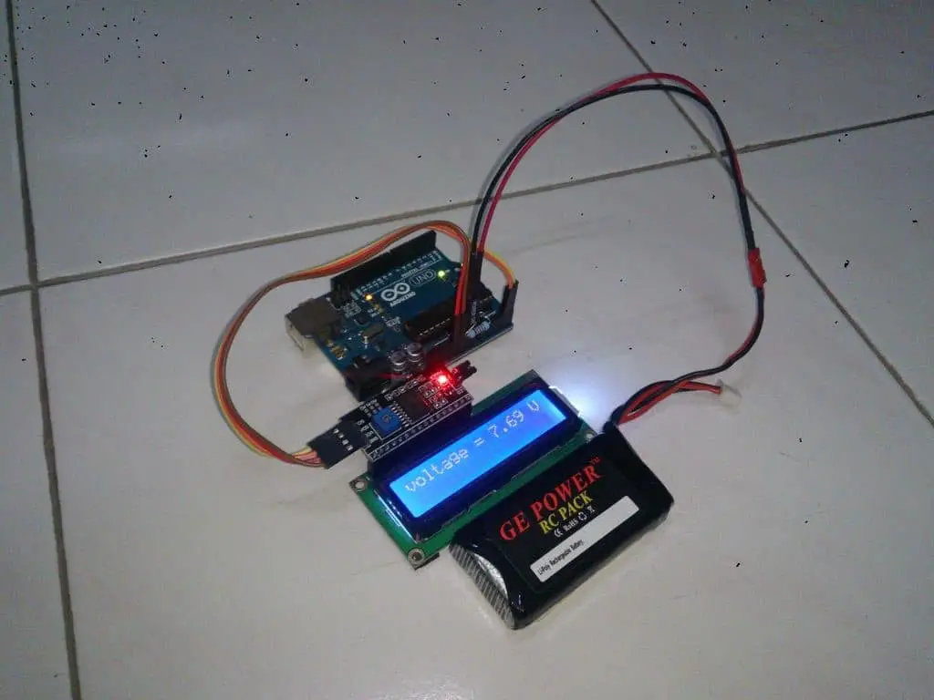
Setup connection
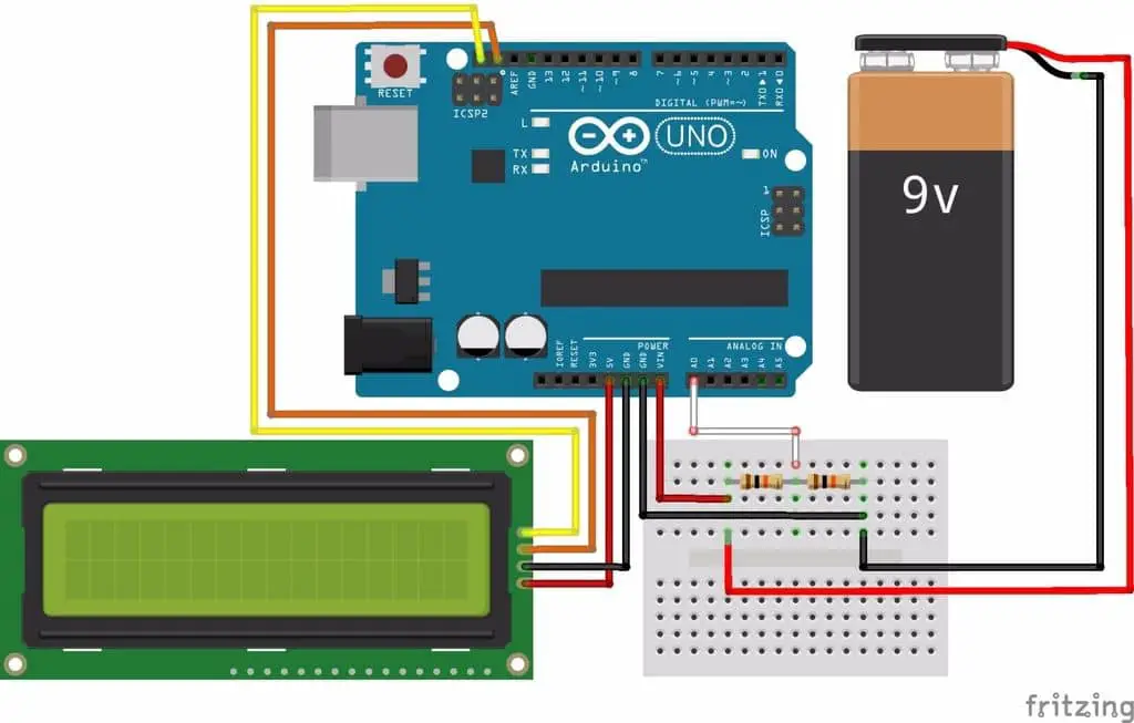
You can see the wire connection is simple in the image above.
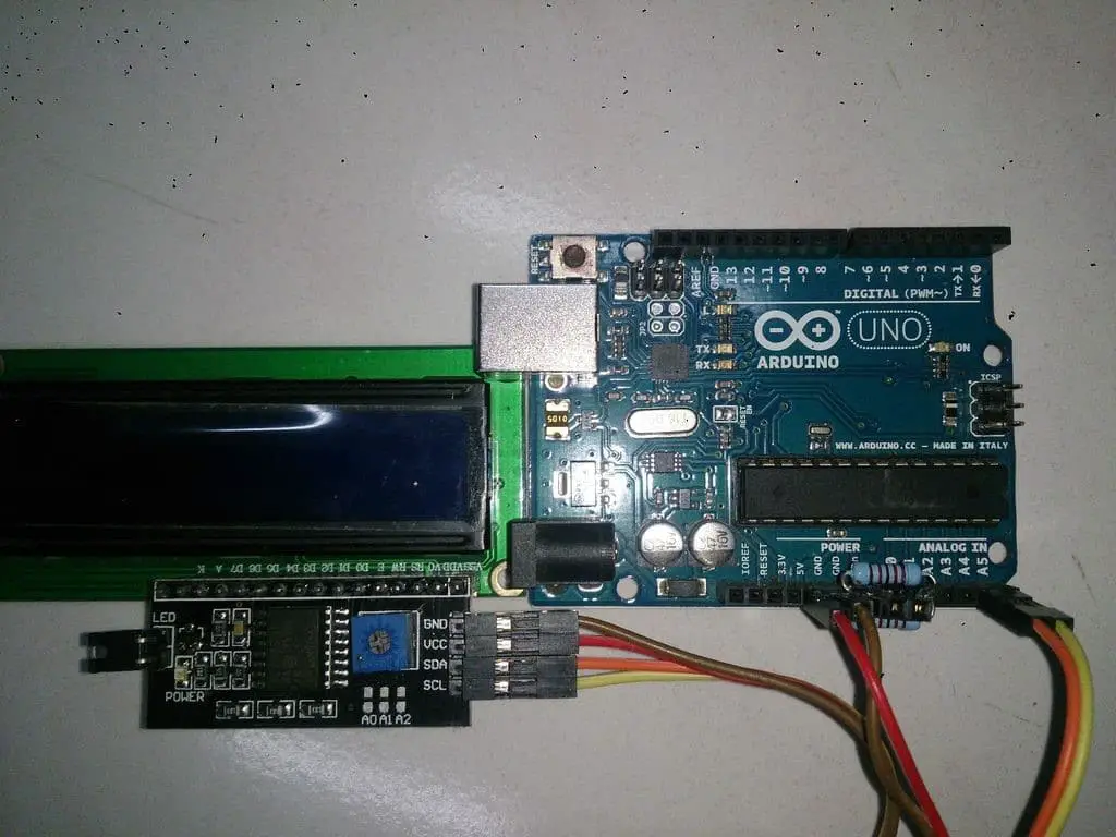
Using a 16×2 LCD with its I2C adapter:
- Adapter GND to Arduino GND.
- Adapter VCC to Arduino 5V.
- Adapter SDA to Arduino A4 (or pins next to the AREF on the digital pin side).
- Connect the SCL adapter to the Arduino A5 (or pins next to the SDA with two pins on the digital pin side of the AREF).
- Connect two 10K resistors in series on the breadboard.
- Connect the middle of the series resistor to Arduino A0.
- Connect one end to the Arduino GND and the other end to the battery – (negative).
- Connect the other end to the Arduino Vin and connect it to the battery + (positive). I think you should connect this after loading Arduino Sketch because I told you my reason before.
Use LED instead of LCD:
- Connect the LED anode (inside the chip) to the Arduino D13.
- Connect the LED cathode (internal bulk) to GND (near D13).
- Connect two 10K resistors in series on the breadboard.
- Connect the middle of the series resistor to Arduino A0.
- Connect one end to the Arduino GND and the other end to the battery – (negative).
- Connect the other end to the Arduino Vin and connect it to the battery + (positive).
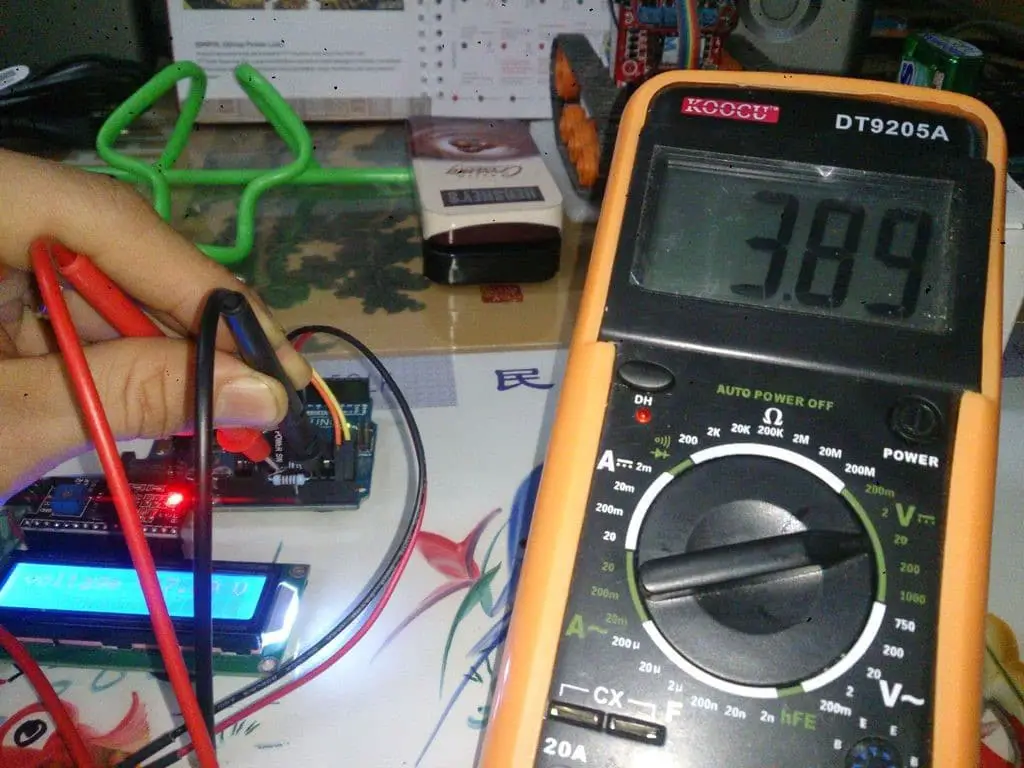
When you insert the battery into the Arduino Vin, it should work immediately to display the battery voltage on your 16×2 LCD as the Arduino is powered by this battery. If it does not work, recheck your connection or you may be using a battery that is less than the 5 volts required for Arduino startup. Try using a different battery or using a voltmeter to check it.
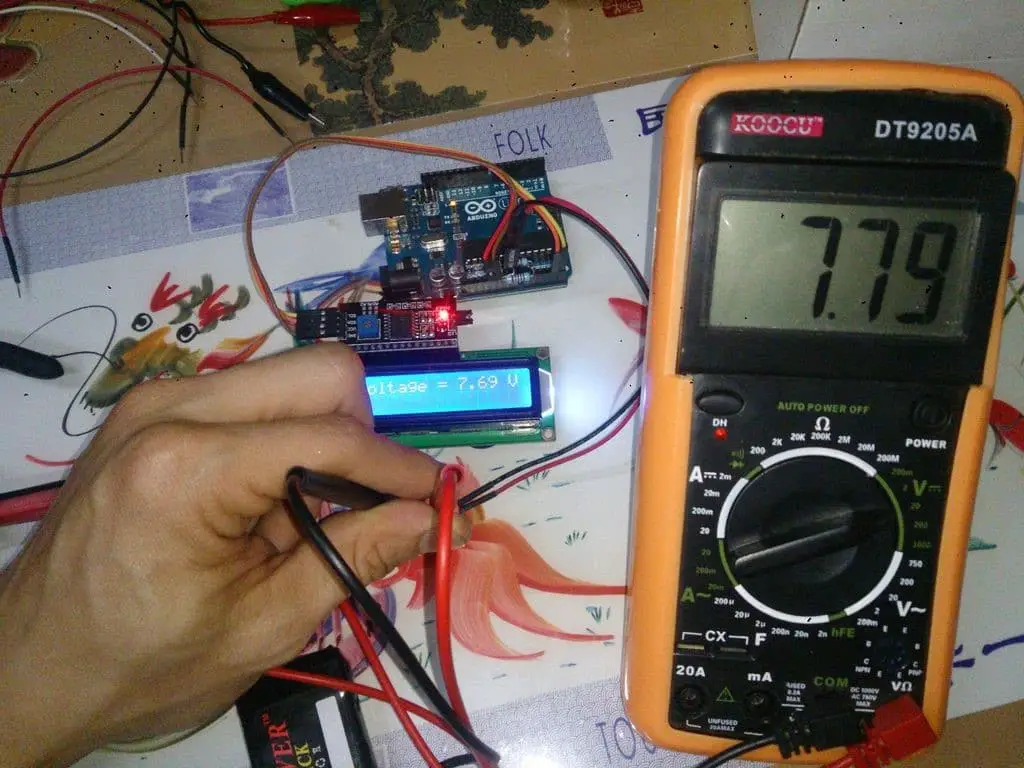
When using a multimeter test, the voltage displayed on the LCD is slightly lower than the multimeter display. We have lost about 0.05V to 0.15V on breadboards and Arduino circuits. But this is not a big deal for me (I do not know how you are), as long as I know if my battery has enough power to run my robot. that’s it.
You may also like to read this
How to Connect your Raspberry Pi and Arduino Together
Build Your Own Vehicle Tracking System using Arduino (Start with Sim808 )


