


Here is just a simple guide on how to use Arduino to create your own mini “security system”. This is just an interesting project, please do not rely on this equipment to ensure the safety of your house! This design uses Arduino, HC-SRO4 ultrasonic sensors, buzzer and some LEDs. Finally, from this tutorial, I hope you learn how to use buzzer and LED to display the distance between the object and the ultrasonic sensor.
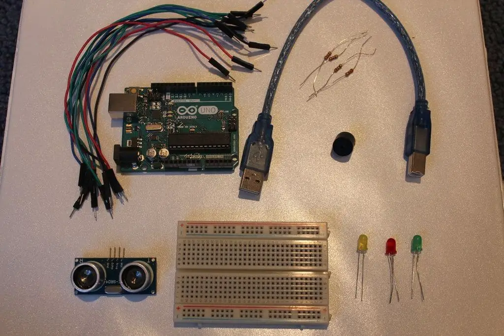
Hardware requirements
- (1x) Arduino Uno (Buy Now)
- (1x) breadboard (Buy Now)
- (1x)HC-SRO4 Ultrasonic Sensor (Buy Now)
- (1x) Buzzer (Buy Now)
- (1x) Green LED (Buy Now)
- (1x) Yellow LED (Buy Now)
- (1x) Red LED (Buy Now)
- (4x) 220 Ohm Resistance (Buy Now)
- (10x) Jumpers (Buy Now)
Note: these are Affiliated links if you buy the things from the given link I would appreciate
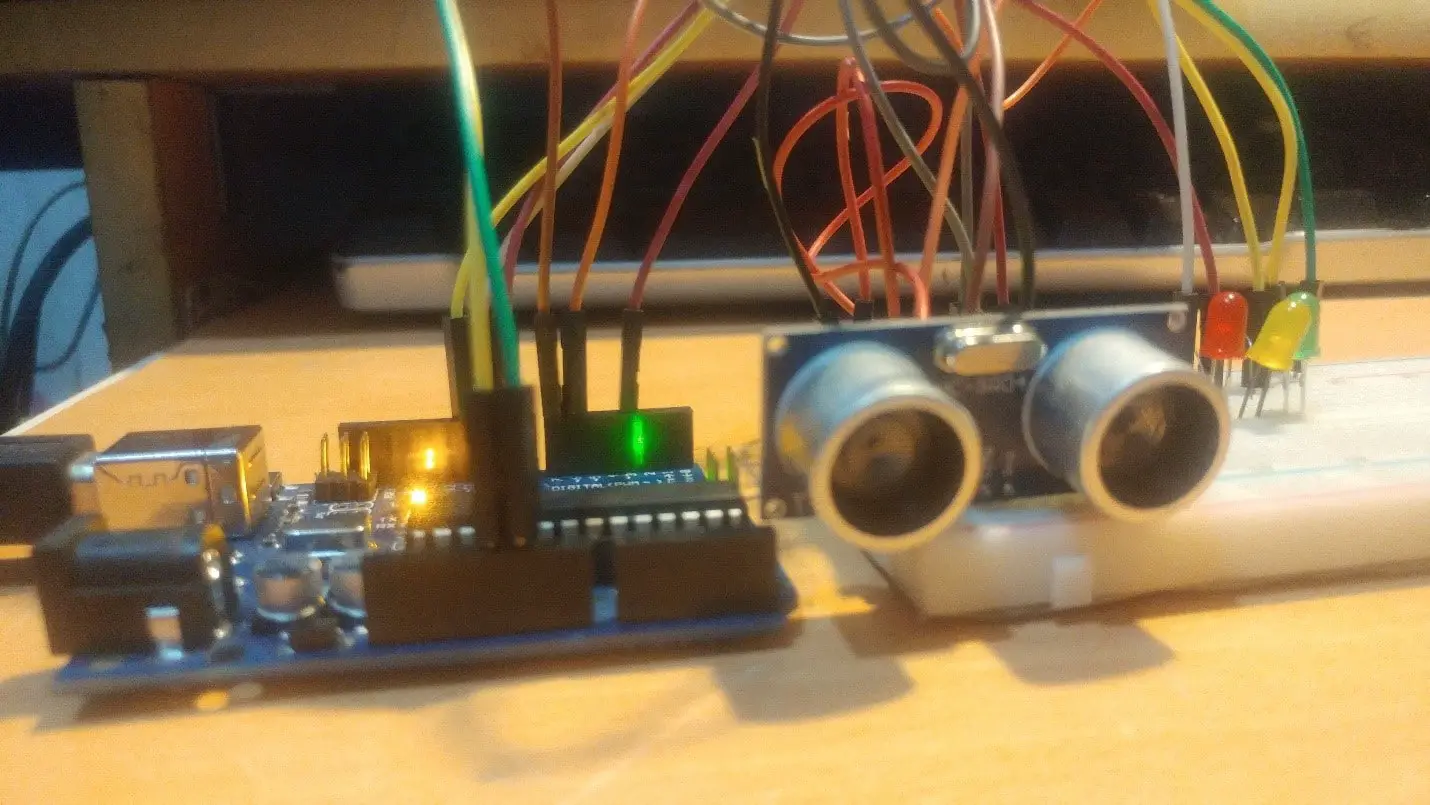
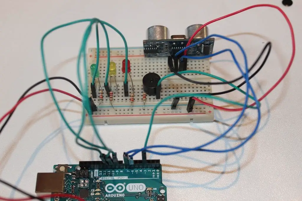
The photo above shows the wiring for this project.
Connection
- Connect the red wire of the 5V pin on the Arduino to the positive channel of the breadboard.
- Connect the black wire from the Arduino’s GND pin to the breadboard’s negative channel
- Buzzer = Pin 3
Ultrasonic sensor:
- Echo = 6th stitch
- Trig = Pin 7
LED indicator:
- RedLED = Pin 9
- YellowLED = Pin 10
- GreenLED = Pin 11
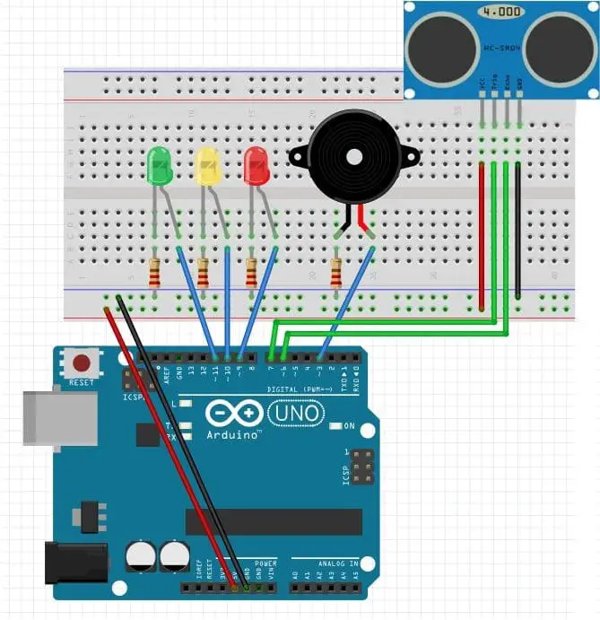
The green wire connected to the LED should be connected to the anode of the LED, and the cathode of the LED should be connected to the cathode of the breadboard using a 220 ohm resistor.
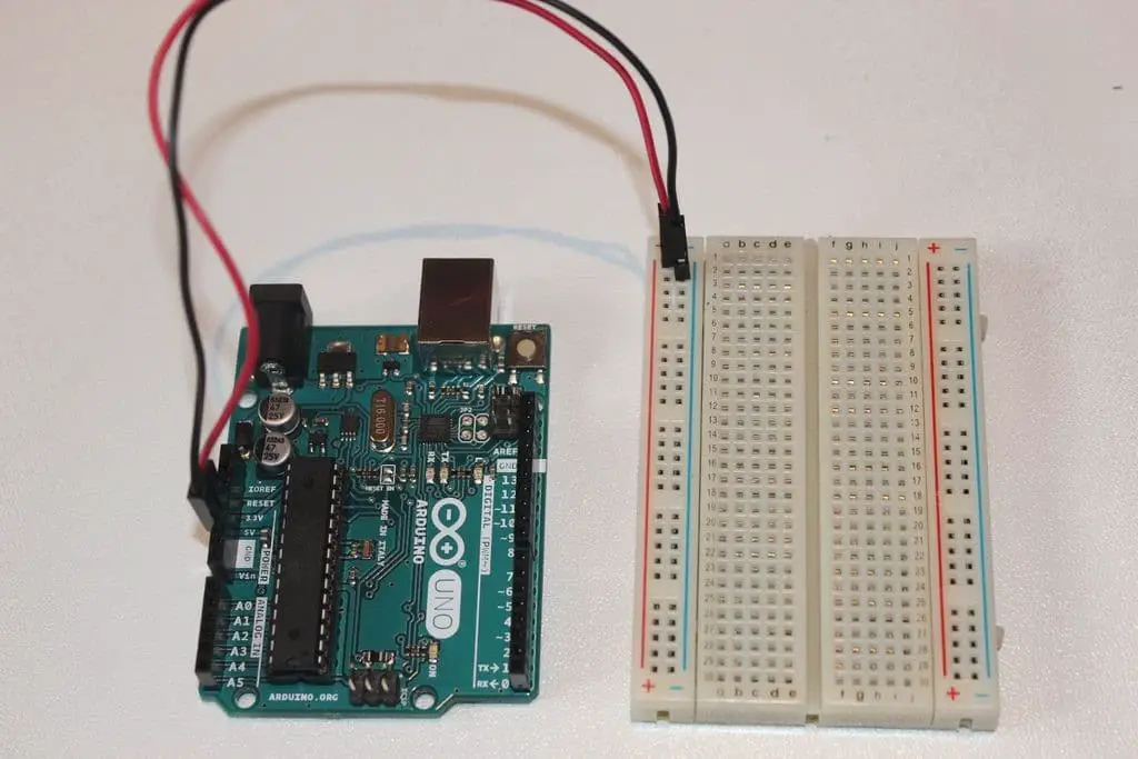
First, let’s connect the 5V and GND pins on the Arduino to the breadboard. As I mentioned earlier, make sure that the wire connected to the 5V pin is connected to the positive channel of the breadboard, and the wire connected to the GND pin is connected to the negative channel of the breadboard.
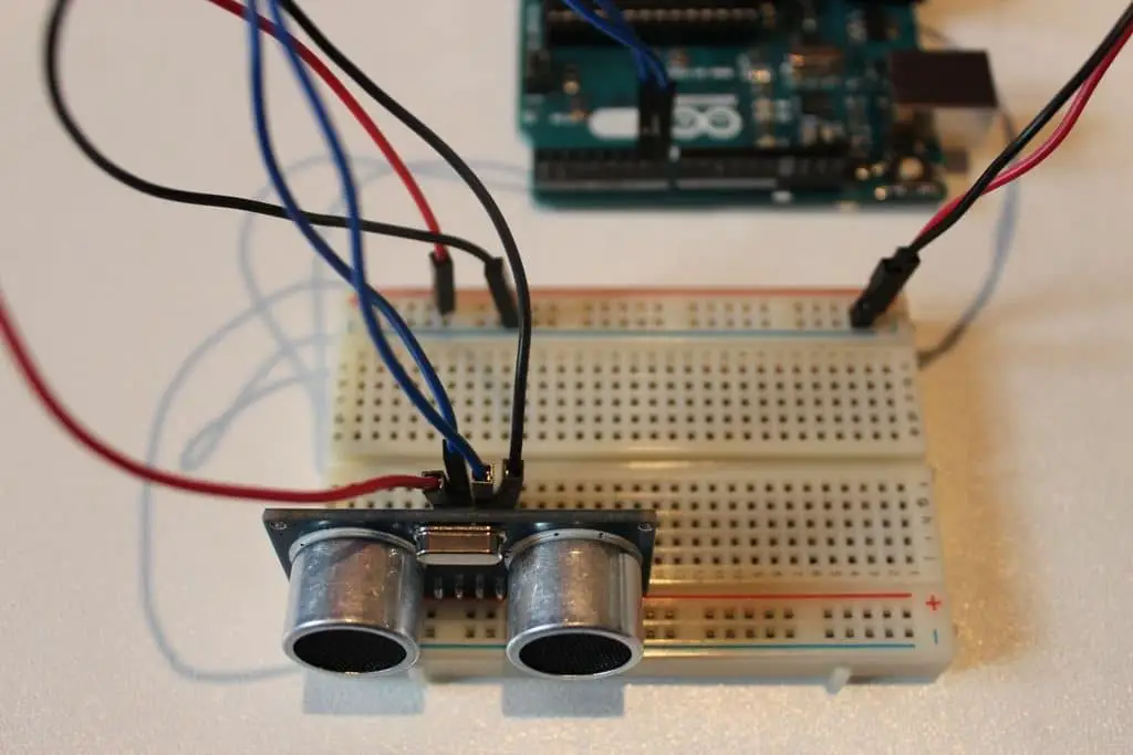
Time to connect the HC-SRO4 ultrasonic sensor! A good tip is to place the ultrasonic sensor as close to the right side of the breadboard as possible and make sure it faces outward. Going back to the setup screen, you should connect the GND pin on the ultrasonic sensor to the negative channel on the breadboard. Next connect the Trig pin on the sensor to pin 6 on the Arduino and the Echo pin on the sensor to pin 7 on the Arduino. Finally, connect the VCC pin on the ultrasonic sensor to the positive channel on the breadboard. If there are any problems that may cause confusion, please refer to the above figure.
The next step is to connect the LEDs to the breadboard and Arduino. If you need it, I highly recommend you to refer to the setup picture (step 2). The additional indicator light is very easy and there are many repetitions. We first connect the green LED. So the way to do this is to connect the anode (longer leg) to the pin 11 on the Arduino with a green wire, and the cathode (shorter pin) to the negative channel on the breadboard, using a 220 ohm resistor. . Then repeat this step for the yellow and red LEDs, making sure to connect the anode (longer leg) of the yellow LED to pin 10 of the Arduino, then connect the anode of the red LED to pin 9. Once there is this, Your settings should look similar to the above picture.
Resistance is not absolutely necessary, but it is highly recommended.
The last part of this setup is to connect the buzzer to the breadboard and Arduino. This is one of the simplest parts of the entire setup. All you need to do is use the green wire to connect the buzzer’s longer arm to the Arduino’s pin 3, and then use a 220 ohm resistor to connect the buzzer’s shorter arm to the breadboard’s negative channel.
It is highly recommended to use a resistor to connect the shorter end of the buzzer to the negative channel of the breadboard. This greatly reduces the volume of the buzzer and prevents it from quickly dying.
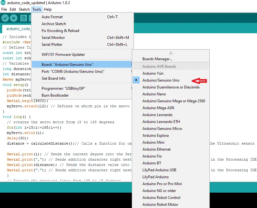
UPLOAD Source Code
Now that you have completed the setup, it is time to write Arduino. Just open the Arduino program on your computer and copy and paste the code below. Feel free to change the distance between the ultrasonic sensor and the volume of the buzzer!
#define trigPin 6
#define echoPin 7
#define GreenLED 11
#define YellowLED 10
#define RedLED 9
#define buzzer 3
int sound = 500;
void setup() {
Serial.begin (9600);
pinMode(trigPin, OUTPUT);
pinMode(echoPin, INPUT);
pinMode(GreenLED, OUTPUT);
pinMode(YellowLED, OUTPUT);
pinMode(RedLED, OUTPUT);
pinMode(buzzer, OUTPUT);
}
void loop() {
long duration, distance;
digitalWrite(trigPin, LOW);
delayMicroseconds(2);
digitalWrite(trigPin, HIGH);
delayMicroseconds(10);
digitalWrite(trigPin, LOW);
duration = pulseIn(echoPin, HIGH);
distance = (duration/5) / 29.1;
if (distance < 50) {
digitalWrite(GreenLED, HIGH);
}
else {
digitalWrite(GreenLED, LOW);
}
if (distance < 20) {
digitalWrite(YellowLED, HIGH);
}
else {
digitalWrite(YellowLED,LOW);
}
if (distance < 5) {
digitalWrite(RedLED, HIGH);
sound = 1000;
}
else {
digitalWrite(RedLED,LOW);
}
if (distance > 5 || distance <= 0){
Serial.println(“Out of range”);
noTone(buzzer);
}
else {
Serial.print(distance);
Serial.println(” cm”);
tone(buzzer, sound);
}
delay(300);
}


Once you have done this, and you have inserted Arduino into your computer, running the code is complete. If you have followed all the instructions correctly, the closer the hand or any object is to the HC-SRO4 ultrasonic sensor, the LED should light gradually until the buzzer goes out when the distance is too close.

You may also like to read these articles


