


In our previous article Raspberry Pi GPIO, Interfacing a switch or an LED to the GPIO header really couldn’t be simpler.
1.Wire in the switch
The first job in interfacing a switch to the Pi is to connect one of the switch’s two terminals to a GPIO pin (which will be configured as an input in the software) and connect the other of its terminals to 0V (GND).
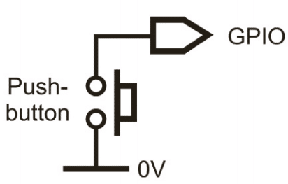
Having done this, the GPIO pin will be connected to 0V, a condition that the software will see as a logic 0, whenever the switch is closed, ie held down in the case of a push button or in its ‘on’ state with a mechanically latching toggle switch.
2. Add a pull-up resistor
Although a GPIO pin wired to a switch and 0V will be at logic 0 when the switch is
closed, it will be ‘floating’ when it’s open.
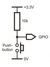
In other words, it wouldn’t be certain whether it would be seen as a 0 or a 1. To overcome this, it must be wired to +3.3V via a resistor, which is referred to as a pull-up resistor.
Now, the GPIO pin will be logic 1 when the switch is open. The resistor value isn’t critical, but 10k is a good choice.
3. Use built-in pull-ups
If you’re wiring the switch to some types of other single-board computer or to the Pi’s GPIO via some logic circuitry, an external pull-up resistor is the only solution.
However, if you’re interfacing directly to a GPIO pin, you can, as an option, enable an internal pull-up resistor in the Pi’s circuitry. The bit of code reproduced here shows how this is done using the RPi.GPIO Python library. The circuit diagrams in the remaining steps assume an external pull-up, but, if you’re using an internal pull-up, just omit the 10k resistor.
GPIO.setup (2, GPIO.IN, pull_up_down=GPIO.
PUD_UP)
# set GPIO 2 as input with pull-up
4. Limit the current
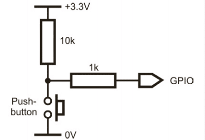
Because GPIO pins are bidirectional, there’s a potential problem if a pin that’s attached to a switch is accidentally configured as an output and set to a logic 1. This will put 3.3V on the pin which, if the switch is then closed, would be connected directly to 0V.
This would cause a high current to flow and, potentially, damage the Pi. Putting a resistor in series with the switch will prevent this, and 1k is the recommended value. The series resistor is also integral to the circuit in the next step, so don’t omit it if you want to add de-bounce circuitry.
5. De-bounce the switch
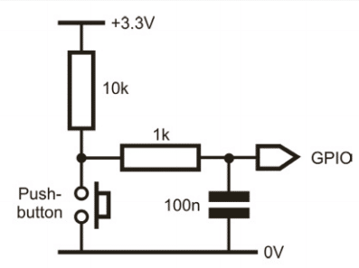
When a switch is operated, the contacts often open and close several times very quickly for a short time.

This is called bounce, and it might cause problems. Perhaps pressing a push button is supposed to turn a LED on or off. Now, if the LED is off and you press and release the push button but it switches closed open-closed-open instead of closed-open, the LED
will switch on and off again very quickly, but it would appear that nothing has happened.
This is remedied by adding a capacitor as shown – a value of 100n is typical if you’re using a 1k current-limiting resistor. Alternatively, software de-bounce can be selected in
the RPi.GPIO library.
6. Use multi-way switches
A multi-way rotary switch is handled in just the same way as a single-way switch except that it connects to several GPIO pins and requires the interface circuitry described earlier for each of those pins.

The circuit diagram shows how this would be done for a four-way switch. De-bounce capacitors aren’t included because the bounce isn’t as much a problem with a multi-way or toggle switch as it is with a push button, because of their mechanically latching nature.
7. Understand LED basics
An LED (light-emitting diode) is a component that produces light when a current flows through it. It’s a polarised device, so its anode must always be connected to the positive supply and its cathode to the negative supply.
A fundamental property of an LED is its forward voltage, which is usually between
1.8V and 3.3V depending on its colour and type. An LED requires this voltage in order to illuminate. Also important is the recommended current, at which its brightness and so on will be quoted. All these parameters are shown in the LED’s specification sheet.
8. Limit the current
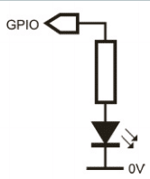
Turning on a LED from a GPIO pin involves configuring the pin as an output and then
outputting a logic 1. This puts 3.3V on the pin, but this will probably exceed the LED’s
forward voltage, thereby causing its maximum current to be exceeded, destroying the LED and possibly damaging the Pi. This is prevented by adding a series resistor which drops the excess voltage. The resistor must drop the difference between 3.3V and the LED’s forward voltage. The value is worked out using Ohm’s law, as described in the next step.
9. Make use of Ohm’s law
First you need to decide the drive current for the LED. This must be less than the LED’s
recommended current and less than the GPIO pin’s maximum of 16mA.
Also, the total current drawn from all GPIO pins must be less than 50mA. 10mA will often give enough light, even if the recommended current is greater. Ohm’s law is summarised as V = I R.
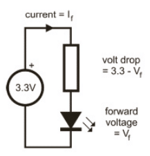
This can be rearranged as R = V / I to give the value of the resistor, R, where V is the voltage that needs to be dropped (ie 3.3V minus the LED’s forward voltage), and I is the drive current.
For example, a forward voltage of 2.0V and a current of 10mA (0.01A) will require a value of (3.3 – 2.0) / 0.01 = 130 ohms.
10. White and blue LEDs

Some LEDs – mainly blue, white and ‘pure green’ – have forward voltages higher than 3.3V, so they can’t be driven directly from a GPIO pin. Even if the value is specified as 3.3V, driving it directly from a GPIO pin would not be safe or reliable. The solution is to drive it from a higher voltage.
I am recommending you to read Make: Sensors: A Hands-On Primer for Monitoring the Real World with Arduino and Raspberry Pi.


