


In this article, we will solve the problem of transmitting a radio signal between two Arduino controllers using a popular 433 MHz transceiver.
In fact, a data transmission device consists of two modules: a receiver and a transmitter. Data can only be transferred in one direction. This is important to understand when using these modules.

For example, you can make remote control from any electronic device, whether it be a mobile robot or, for example, a TV. In this case, the data will be transmitted from the control panel to the device.
Another option is to transmit signals from wireless sensors to a data acquisition system. Here the route is already changing, now the transmitter is on the side of the sensor, and the receiver is on the side of the collection system.
Modules can have different names: MX-05V, XD-RF-5V, XY-FST, XY-MK-5V, etc., but they all have approximately the same appearance and numbering of contacts. Also, two frequencies of radio modules are common: 433 MHz and 315 MHz
Collect the Hardware
- 2X Arduino UNO (View on Amazon)
- 433 MHz Radio Module (View on Amazon)
1.Connection
The transmitter has only three outputs: Gnd, Vcc and Data.
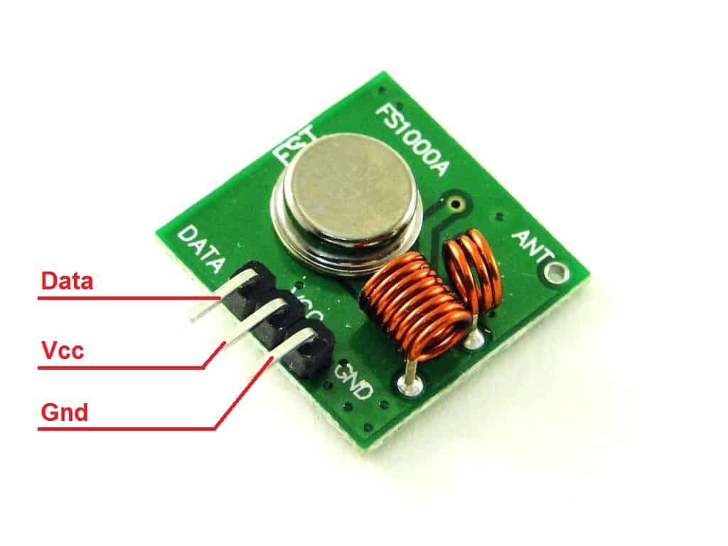
We will connect them to the first Arduino board according to the fritzing:
| MX-05V 433MHz Transmitter | GND | VCC | Data |
| Arduino Uno | GND | + 5V | 2 |
The receiver has four outputs, but one is not used.
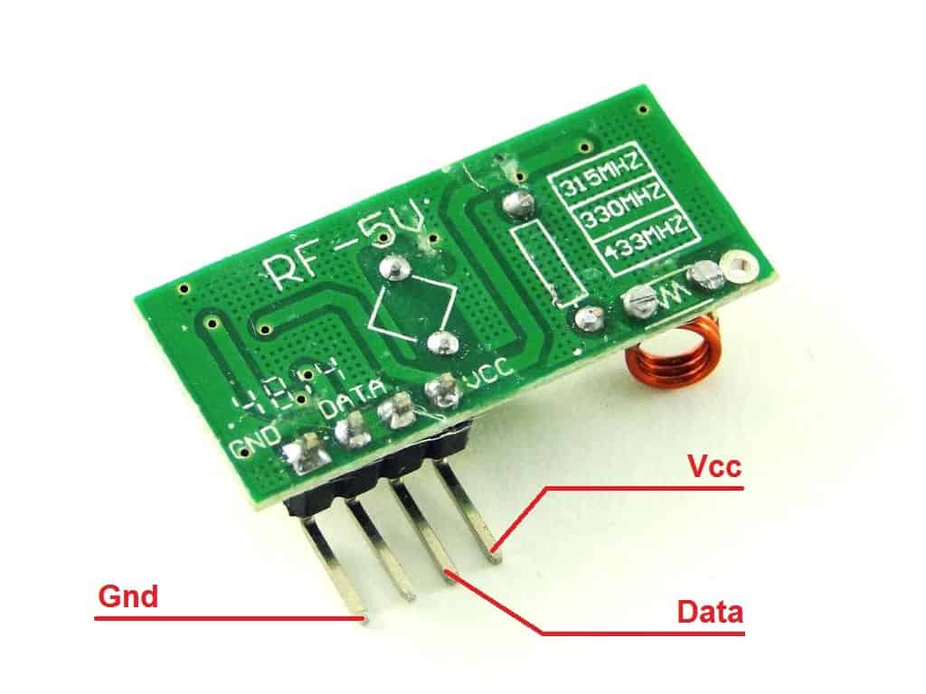
The connection scheme to the second Arduino board is identical to the first one:
| XD-RF-5V 433MHz Receiver | GND | VCC | Data |
| Arduino Uno №2 | GND | + 5V | 2 |
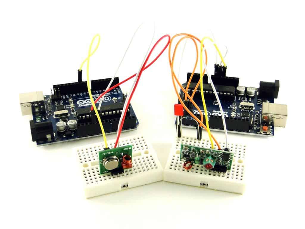
We just assemble both devices on a breadboard and proceed to write programs.
2.Program for transmitter
To work with radio modules, we will use the RCSwitch library. Let’s write a program that will send two different messages, in turn, every second.
#include <RCSwitch.h>
RCSwitch mySwitch = RCSwitch ();
void setup () {
mySwitch.enableTransmit (2);
}
void loop () {
mySwitch.send (B0100, 4);
delay (1000);
mySwitch.send (B1000, 4);
delay (1000);
}
Working of the Code
Let’s start analyzing the program. The first thing we did was declare an object to work with the transmitter and called it mySwitch.
RCSwitch mySwitch = RCSwitch ();
Then, inside the standard setup function, turned on the transmitter and indicated the output to which it is connected:
mySwitch.enableTransmit (2);
Finally, in the main loop of the loop program, we are sending the first message, and then the second using the send function:
mySwitch.send (B1000, 4);
The send function has two arguments. The first is a message being sent, which will be broadcast as a burst of pulses. The second argument is the size of the bundle being sent.
In our program, we just specified messages in binary number format. This is indicated by the English letter “B” at the beginning of the B1000 code. In the decimal representation, this number will become a figure of eight. So we could call the send function like this:
mySwitch.send (8, 4);
Also, send can accept binary strings:
mySwitch.send (“1000”, 4);
3.Receiver program
Now we will write a program for the receiver. To demonstrate the fact of transmission, we will turn on the LED connected to pin 3 on the Arduino board. If the receiver caught the code B1000 – turn on the LED, and if B0100 – turn off.
#include <RCSwitch.h>
RCSwitch mySwitch = RCSwitch ();
void setup () {
pinMode (3, OUTPUT);
mySwitch.enableReceive (0);
}
void loop () {
if (mySwitch.available ()) {
int value = mySwitch.getReceivedValue ();
if (value == B1000)
digitalWrite (3, HIGH);
else if (value == B0100)
digitalWrite (3, LOW);
mySwitch.resetAvailable ();
}
}
The available function returns true if the transmitter has received at least some data:
mySwitch.available ()
The getReceivedValue function retrieves one packet from the data stream and decodes it into a number. In the program, we assign the resulting number to the variable value :
int value = mySwitch.getReceivedValue ();
Related Post How to Control Arduino and led lights with a TV Remote
The task we can Perform
Now we can try to practice and can develop many different devices. Here are a few ideas.
- Remote for the lamp. On the receiver side, there is a relay module that is connected to the luminaire power supply (carefully, 220 Volts!). On the transmitter side: a clock button. Write a program for the receiver and transmitter, which at the touch of a button will include a remote relay. When you press the button again, the relay will turn off.
- Outdoor thermometer with a radio channel. Place a temperature sensor on the transmitter side. Provide autonomous power from batteries. On the receiver side: character LCD display. Write programs for the receiver and transmitter that will allow you to display temperature readings from a remote sensor on the display.
Conclusion
So now we just learned a simple and inexpensive way to transmit data over a distance. Unfortunately, the transmission speed and distance in such radio modules are very limited, so that we cannot fully control, for example, a quadcopter. However, to make a radio control to control a simple household appliance: a lamp, a fan or a TV, we can do.
On the basis of transceivers with a frequency of 433 MHz and 315 MHz, most radio channel control panels operate. With Arduino and receiver, we can decode the control signals and repeat them. More about how to do this, we will write in one of the following lessons!