


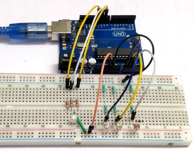
What if we can use a single RGB LED to generate different colors and make our room corners more attractive? So this is a simple Arduino-based color mixing light that changes color when the room’s light changes. Therefore, this light will automatically change color according to the lighting conditions of the room.
Each color is a combination of red, green and blue. Therefore, we can generate any color by using red, green and blue. So here we will change the PWM, the light intensity on the LDR. This will further change the intensity of red, green and blue in the RGB LED and will produce different colors.
The table below shows the color combinations for each duty cycle change.
Hardware Requirements
- Arduino UNO View on Amazon
- Breadboard View on Amazon
- 3x 220-ohm resistor View on Amazon
- 3x 1 kΩ resistor View on Amazon
- Jumper Wires View on Amazon
- 3x LDR View on Amazon
- 3 colored bars (red, green, blue) View on Amazon
- 1x RGB LED View on Amazon
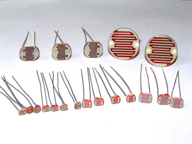
LDR:
We will use a photoresistor (or photoresistor, LDR or photoconductive cell) in this circuit. The LDR is made of a semiconductor material to give it a photosensitive property. The working principle of these LDR or PHOTO RESISTORS is “photoconductivity”. The principle now states that whenever the light falls on the surface of the LDR (in this case), the conductance of the component increases, or in other words, when the light falls on the surface of the LDR, the resistance of the LDR decreases. Since the LDR is a characteristic of a semiconductor material used on the surface, such a characteristic that the resistance of the LDR is lowered is achieved.
There are three LDR sensors for controlling the brightness of the red, green and blue LEDs inside the RGB Led. Learn more about using the Arduino to control LDR here.
 RGB LED:
 RGB LED:
There are two types of RGB LEDs, one is common cathode type (common cathode type), and the other is common anode type (common anode type). In CC (common cathode or common cathode), there will be three positive terminals, each terminal representing one color and one negative terminal representing all three colors.
- RGB LED common anode lead wire
- Common anode RGB LED
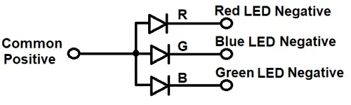
In our circuit we will use the CA (common anode or common anode) type. In the Common Anode type, if we want the RED LED to turn on, we need to ground the RED LED pin and power the common positive. This is true for all LEDs. Learn to interface RGB LEDs with Arduino here.
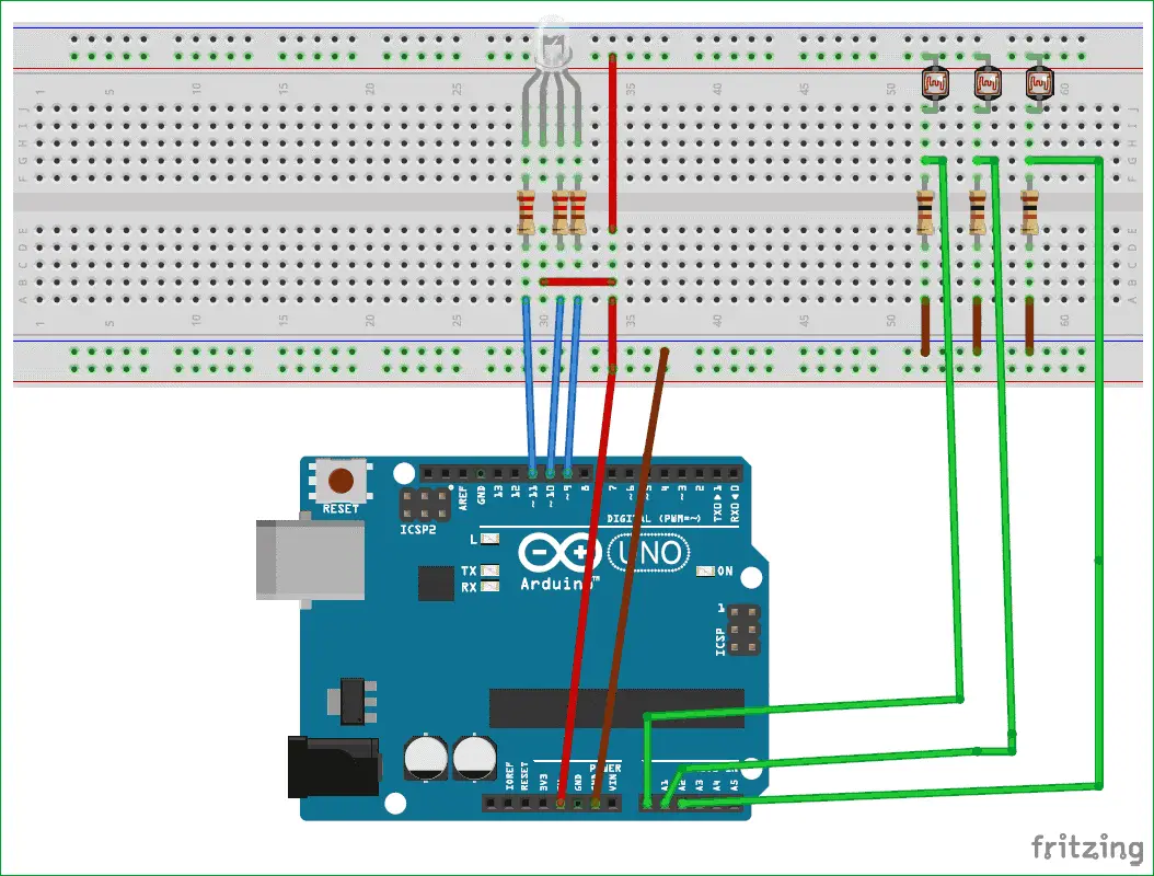
Circuit schematic:

Arduino color mixing lamp uses RGB and LDR circuit diagram
The complete circuit diagram for this project is as described above. The +5V and ground connections shown in the circuit diagram are available from the 5V and ground pins of the Arduino. The Arduino itself can be powered by a laptop or a DC jack using a 12V adapter or 9V battery.
Upload Source Code
const byte red_sensor_pin = A0;
const byte green_sensor_pin = A1;
const byte blue_sensor_pin = A2;
const byte green_led_pin = 9;
const byte blue_led_pin = 10;
const byte red_led_pin = 11;
unsigned int red_led_value = 0;
unsigned int blue_led_value = 0;
unsigned int green_led_value = 0;
unsigned int red_sensor_value = 0;
unsigned int blue_sensor_value = 0;
unsigned int green_sensor_value = 0;
void setup() {
pinMode(red_led_pin,OUTPUT);
pinMode(blue_led_pin,OUTPUT);
pinMode(green_led_pin,OUTPUT);
Serial.begin(9600);
}
void loop() {
red_sensor_value = analogRead(red_sensor_pin);
delay(50);
blue_sensor_value = analogRead(blue_sensor_pin);
delay(50);
green_sensor_value = analogRead(green_sensor_pin);
// print those values onto the serial monitor
Serial.println(“Raw Sensor Values:”);
Serial.print(“\t Red: “);
Serial.print(red_sensor_value);
Serial.print(“\t Blue: “);
Serial.print(blue_sensor_value);
Serial.print(“\t Green: “);
Serial.println(green_sensor_value);
// convert from 0-1023 to 0-255
red_led_value = red_sensor_value / 4; // define Red LED
blue_led_value = blue_sensor_value / 4; // define Blue LED
green_led_value = green_sensor_value / 4; // define Green LEd
// print mapped values to serial monitor
Serial.println(“Mapped Sensor Values:”);
Serial.print(“\t Red: “);
Serial.print(red_led_value);
Serial.print(“\t Blue: “);
Serial.print(blue_led_value);
Serial.print(“\t Green: “);
Serial.println(green_led_value);
// use analogWrite() to set output for RGB LED
analogWrite(red_led_pin,red_led_value); // indicate red LED
analogWrite(blue_led_pin,blue_led_value); // indicate blue LED
analogWrite(green_led_pin,green_led_value); // indicate green
}
You may also like to read these projects
Build Real Ghost Detector: Arduino EMF (ELECTROMAGNETIC FIELD) DETECTOR
How to Drive and Build Project with Nokia 5110 LCD using Arduino


