


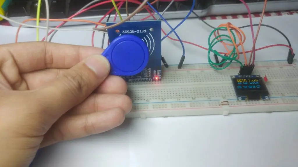
In this article, We will use RFID tags on the Arduino. I have built a simple project that reads the unique ID (UID) of each RFID tag that we place near the reader and displays it on the OLED display. If the tag’s UID is equal to the predefined value stored in the Arduino’s memory, we will see the “Unlocked” message in the display. If the card’s unique ID does not equal the predefined value, the unlock message is not displayed.
There is a lot of content to introduce, so let’s get started!
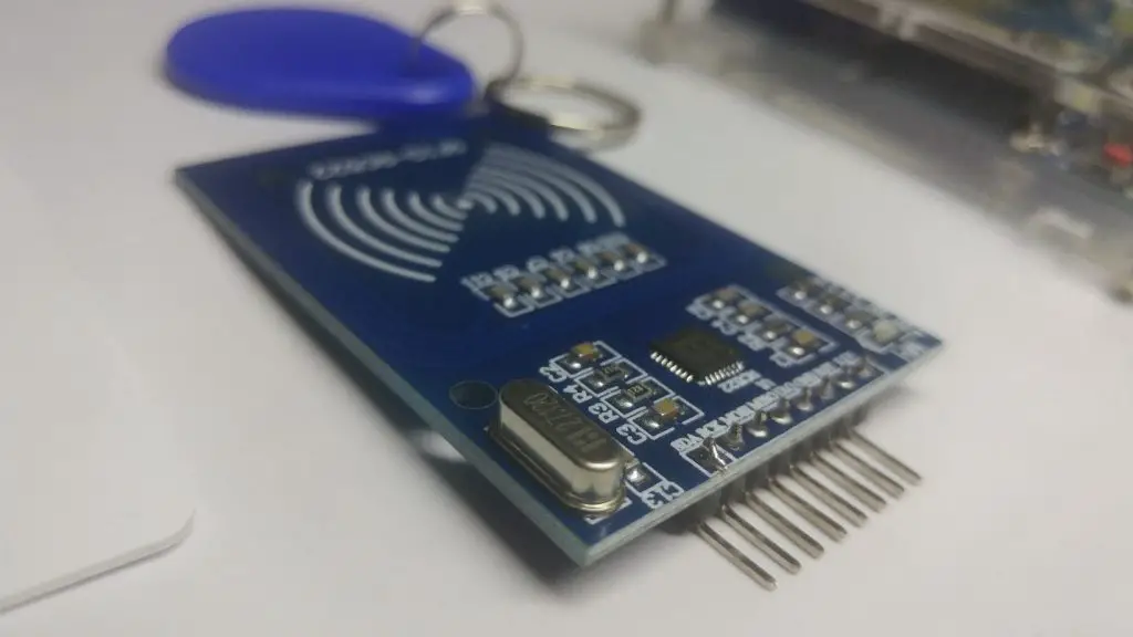
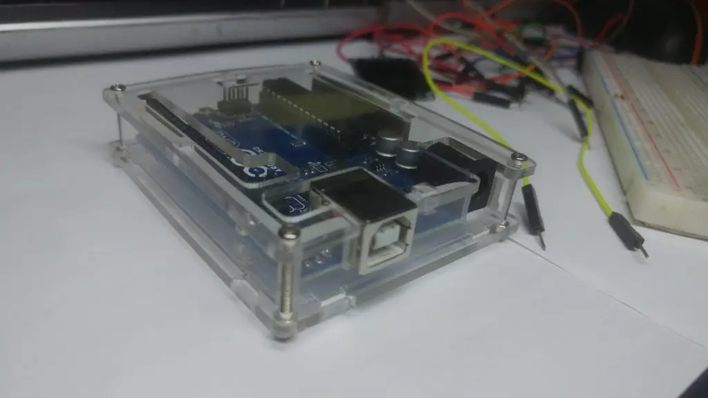
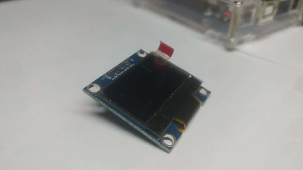
Collecting hardware
Wiring
The connection to the Arduino Uno board is very simple. First, let’s connect the powerful features of the reader and the monitor.
Be careful, the RFID reader must be connected to the Arduino Uno’s 3.3V output, or it will be destroyed. Since the monitor can also work at 3.3V, we connect the Vcc of the two modules to the breadboard track. Then, the rail is connected to the Arduino Uno’s 3.3V output. Next, we connect the two GNDs to the breadboard GND rail. Then we connect the breadboard’s GND rail to the Arduino GND.
OLED Displays – Arduino
- Vcc—–>3V
- GND—–>GND
- SCL —–> Analog Pin 5
- SDA —–> Analog Pin 4
RFID Reader – Arduino
- RST —–> Digital Pin 9
- IRQ —–> not connected
- MISO—–> Digital Pin 12
- MOSI —–> Digital Pin 11
- SCK —–> Digital Pin 13
- SDA —–> Digital Pin 10
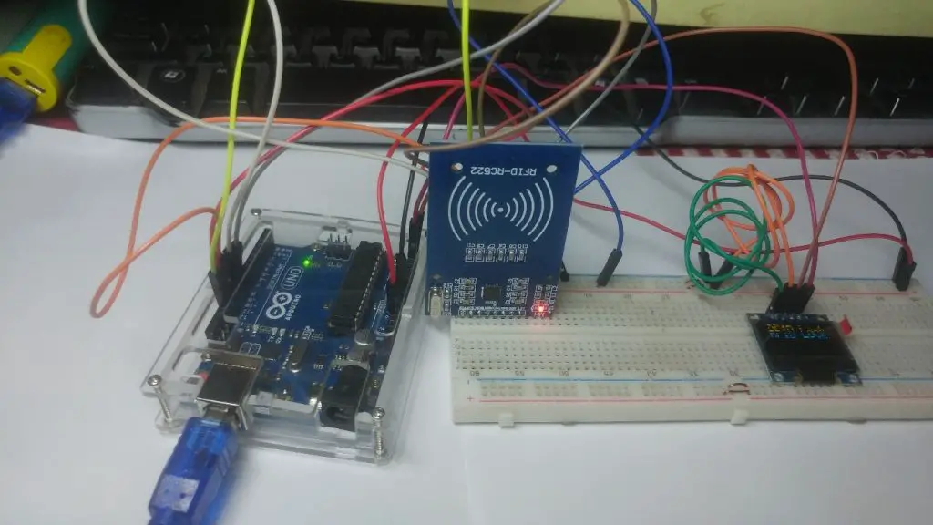
The RFID reader module uses the SPI interface to communicate with the Arduino. So we want to use Arduino UNO’s hardware SPI pins. The RST pin goes to digital pin 9. The IRQ pin remains unconnected. The MISO pin goes to the digital pin 12. The MOSI pin goes to the digital pin 11. The SCK pin goes to the digital pin 13. Finally, the SDA pin goes to the digital pin 10. That’s it. RFID reader is connected. We must now connect the OLED display to the Arduino using the I2C interface. Therefore, the SCL pin of the display is connected to analog pin 5 and the SDA pin of the display is connected to the analog pin 4. If we start the project now and place the RFID card close to the reader, we can see that the project is working properly! Now it’s time to view the project’s code.
Upload source code
#include <MFRC522.h>
#include <Adafruit_GFX.h>
#include <Adafruit_SSD1306.h>
#include <SPI.h>
#define OLED_RESET 4
Adafruit_SSD1306 display(OLED_RESET);
#define SS_PIN 10
#define RST_PIN 9
MFRC522 rfid(SS_PIN, RST_PIN); // Instance of the class
MFRC522::MIFARE_Key key;
int code[] = {69,141,8,136}; //This is the stored UID
int codeRead = 0;
String uidString;
void setup() {
Serial.begin(9600);
SPI.begin(); // Init SPI bus
rfid.PCD_Init(); // Init MFRC522
display.begin(SSD1306_SWITCHCAPVCC, 0x3C); // initialize with the I2C addr 0x3D (for the 128×64)
// Clear the buffer.
display.clearDisplay();
display.display();
display.setTextColor(WHITE); // or BLACK);
display.setTextSize(2);
display.setCursor(10,0);
display.print(“RFID Lock”);
display.display();
}
void loop() {
if( rfid.PICC_IsNewCardPresent())
{
readRFID();
}
delay(100);
}
void readRFID()
{
rfid.PICC_ReadCardSerial();
Serial.print(F(“\nPICC type: “));
MFRC522::PICC_Type piccType = rfid.PICC_GetType(rfid.uid.sak);
Serial.println(rfid.PICC_GetTypeName(piccType));
// Check is the PICC of Classic MIFARE type
if (piccType != MFRC522::PICC_TYPE_MIFARE_MINI &&
piccType != MFRC522::PICC_TYPE_MIFARE_1K &&
piccType != MFRC522::PICC_TYPE_MIFARE_4K) {
Serial.println(F(“Your tag is not of type MIFARE Classic.”));
return;
}
clearUID();
Serial.println(“Scanned PICC’s UID:”);
printDec(rfid.uid.uidByte, rfid.uid.size);
uidString = String(rfid.uid.uidByte[0])+” “+String(rfid.uid.uidByte[1])+” “+String(rfid.uid.uidByte[2])+ ” “+String(rfid.uid.uidByte[3]);
printUID();
int i = 0;
boolean match = true;
while(i<rfid.uid.size)
{
if(!(rfid.uid.uidByte[i] == code[i]))
{
match = false;
}
i++;
}
if(match)
{
Serial.println(“\nI know this card!”);
printUnlockMessage();
}else
{
Serial.println(“\nUnknown Card”);
}
// Halt PICC
rfid.PICC_HaltA();
// Stop encryption on PCD
rfid.PCD_StopCrypto1();
}
void printDec(byte *buffer, byte bufferSize) {
for (byte i = 0; i < bufferSize; i++) {
Serial.print(buffer[i] < 0x10 ? ” 0″ : ” “);
Serial.print(buffer[i], DEC);
}
}
void clearUID()
{
display.setTextColor(BLACK); // or BLACK);
display.setTextSize(1);
display.setCursor(30,20);
display.print(uidString);
display.display();
}
void printUID()
{
display.setTextColor(WHITE); // or BLACK);
display.setTextSize(1);
display.setCursor(0,20);
display.print(“UID: “);
display.setCursor(30,20);
display.print(uidString);
display.display();
}
void printUnlockMessage()
{
display.display();
display.setTextColor(BLACK); // or BLACK);
display.setTextSize(2);
display.setCursor(10,0);
display.print(“RFID Lock”);
display.display();
display.setTextColor(WHITE); // or BLACK);
display.setTextSize(2);
display.setCursor(10,0);
display.print(“Unlocked”);
display.display();
delay(2000);
display.setTextColor(BLACK); // or BLACK);
display.setTextSize(2);
display.setCursor(10,0);
display.print(“Unlocked”);
display.setTextColor(WHITE); // or BLACK);
display.setTextSize(2);
display.setCursor(10,0);
display.print(“RFID Lock”);
display.display();
}
Resource
Special Thanks to this tutorial educ8s.tv its Helps a lot.
You may also like to read these awesome projects
How to Build Plant Automation system with Arduino and Moisture sensor
How to Drive and Build Project with Nokia 5110 LCD using Arduino


