


This tutorial demonstrates how to connect an analog sensor to a Raspberry Pi as well as I will deploy the project of water pressure and water level system using the raspberry pi. In particular, I will use water level/detection sensors and 200 PSI pressure sensors.
Let’s Start
Collect Hardware
- Raspberry Pi (Buy Amazon)
- SEN-AP006G (Buy Amazon)
- MCp3002 (Buy Amazon)
- ADS1115 (Buy Amazon)
- Level Shifter (Buy Amazon)
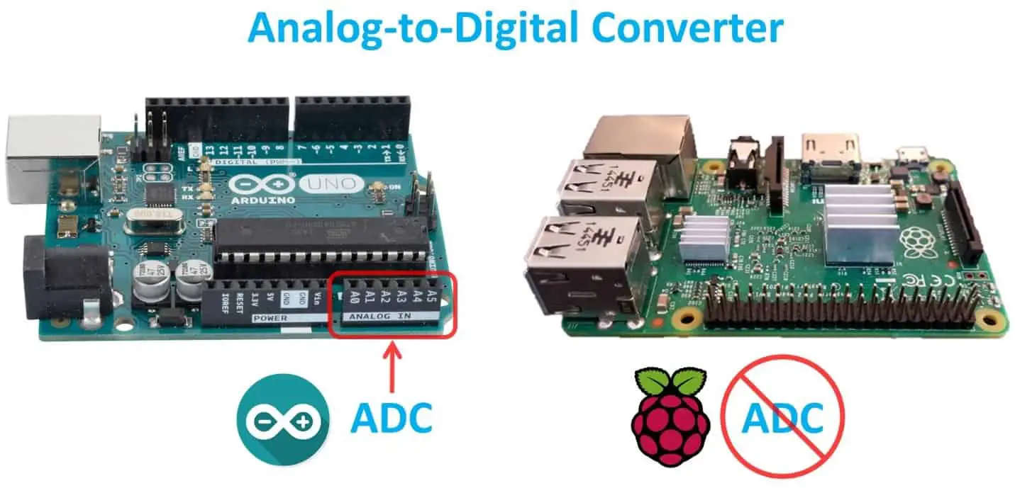
Unlike Arduino, the Raspberry Pi does not have an ADC and represents an analog-to-digital converter. The ADC measures the voltage on the pin and converts it to digital. You can use analog ADC pins to plug analog sensors directly into the Arduino. Raspberry pie requires extra steps.
So why use analog sensors if it works more and Pi does not even have an ADC? Among other things, they are often easier to come by, some are more suitable for a particular environment, and may be cheaper. Sometimes there is no equivalent of the number.

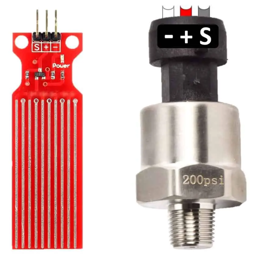
There is a simulated water level and a simulated pressure sensor, I have an eBay. I did search for equivalent numbers, but this is the best I can find at a reasonable price. Both devices output a voltage on the Spin that corresponds to the water level or pressure value. If there is a leak, I’ll hang them in the house, warn me and monitor the pressure on the piping system.
There are several ways to connect the analog device to the Pi. You can try the RC charging circuit, but only use resistors like the Koolance SEN-AP006G. Because of their output voltage, they can not be used for the above level and pressure sensors.
The charging circuit calculates the programming cycle required to charge the capacitor, which varies according to the resistance. It’s better on microcontrollers than on SoCs.
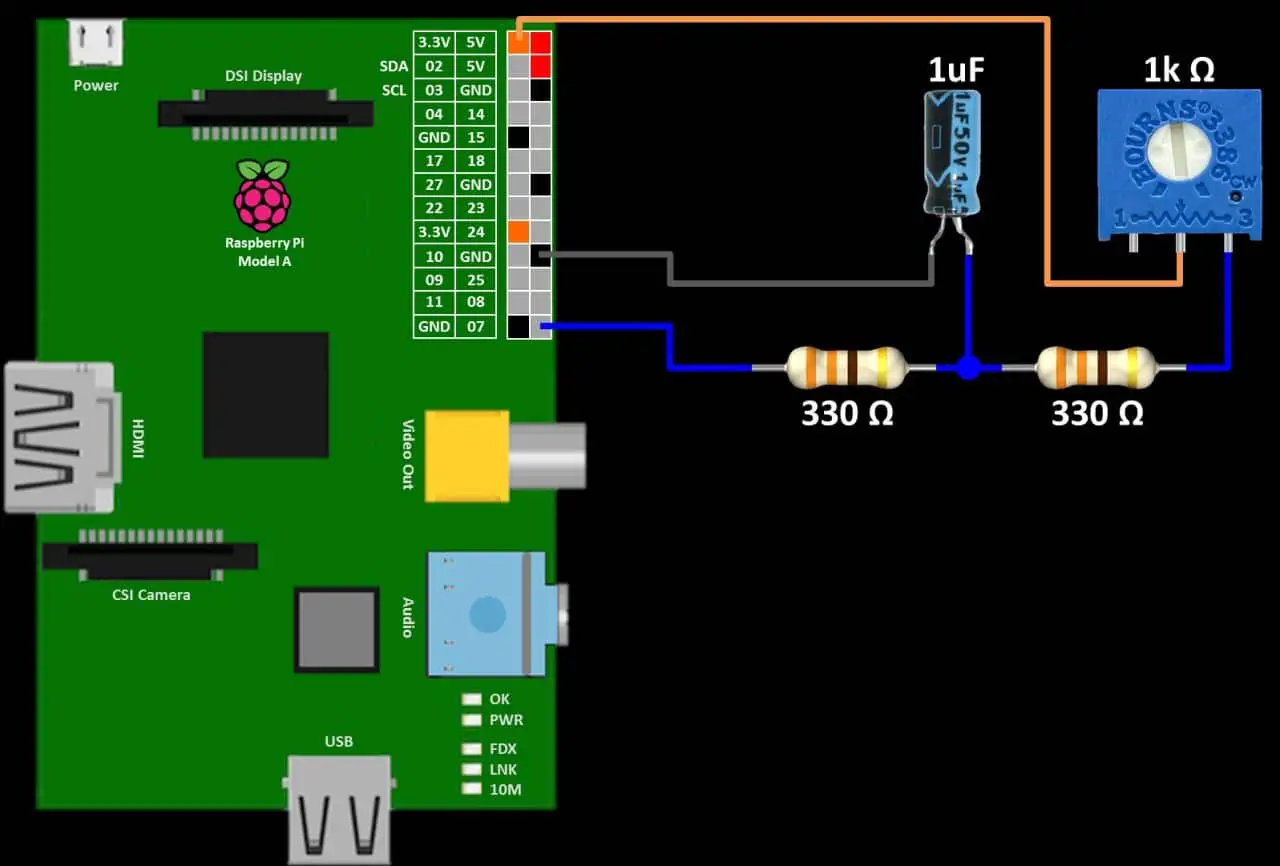
They are often inaccurate on Pi because its operating system may interfere with counting, especially on multicore chips on Python and the new Pi. Here is an example circuit, but I do not recommend this method:
The python code for the RC charging circuit switches the analog signal between the GPIO monitor output and the input. It then counts the number of program cycles until GPIO goes high. This number corresponds to a voltage.
import RPi.GPIO as GPIO
from time import sleep
GPIO.setmode(GPIO.BCM)
try:
while 1:
count = 0
GPIO.setup(21, GPIO.OUT)
GPIO.output(21, GPIO.LOW)
sleep(0.05)
GPIO.setup(21, GPIO.IN)
while(GPIO.input(21) == GPIO.LOW):
count += 1
print(count)
sleep(1)
except KeyboardInterrupt:
print (“\nCtrl-C pressed. Program exiting…”)
finally:
GPIO.cleanup() # run on exit
Another solution is to use a microcontroller with an ADC, such as an Arduino. It polls the analog sensor and sends the result to Pi via SPI.
This is a more advanced technique I’ve covered in my previous video Raspberry Pi AVR Programmer & SPI Tutorial. Therefore, this video will highlight special ADCs such as the MCP3002 and ADS1115. These devices are cheap and easy to use.
The MCP3002 is a 10-bit resolution SPI analog-to-digital converter chip with two ADC channels.
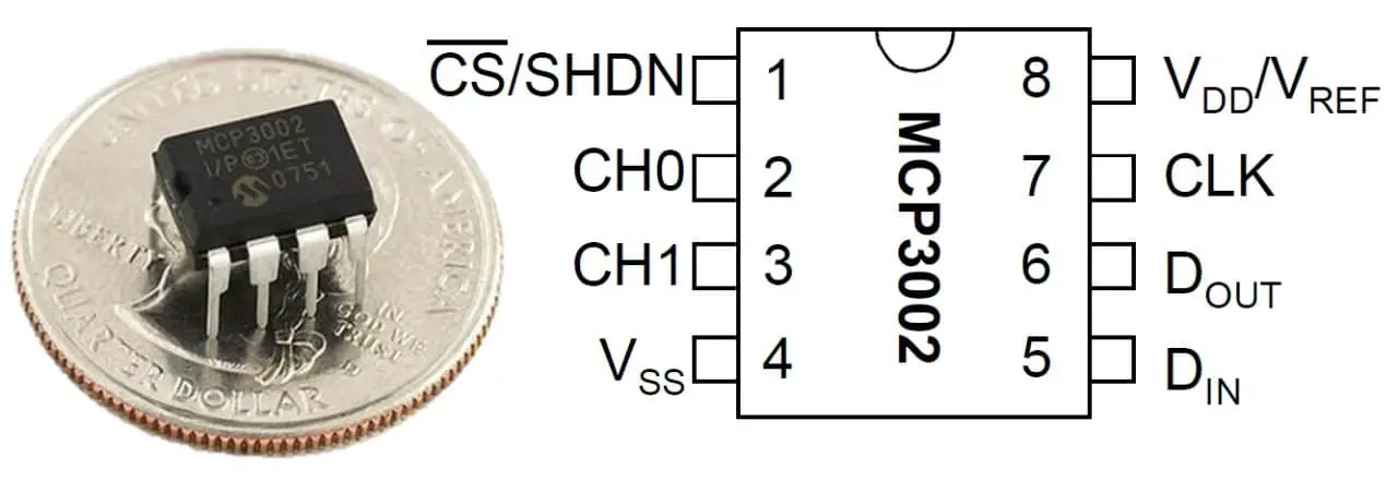
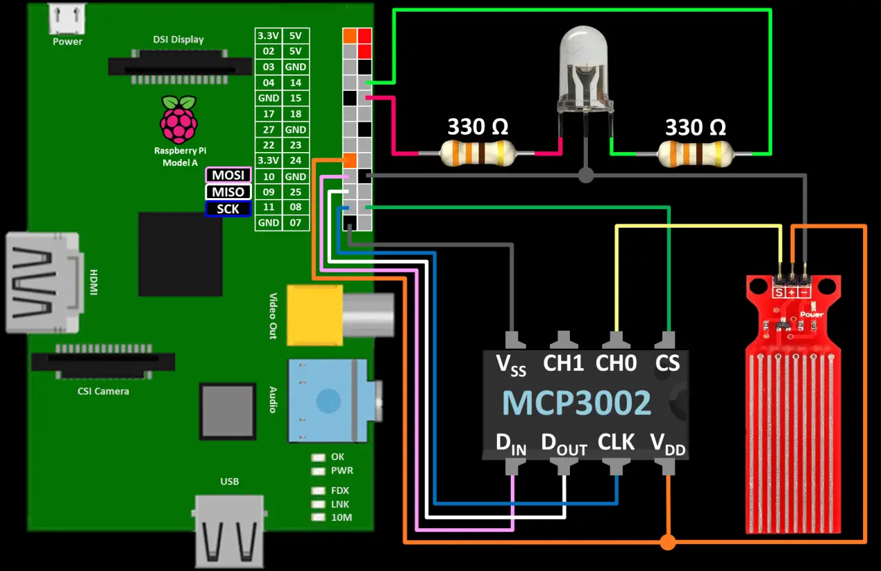
The MCP3002 is connected using Pi’s hardware SPI GPIO pins. DIN to GPIO 10 (MOSI: master-slave input). DOUT to GPIO 9 (MISO: master slave output). CLK to GPIO 11 (SCK: Serial Clock). CS enters GPIO 8 (chip enable is often called chip select).
The voltage on the VDD pin is 3.3 V and the VSS pin is grounded. The “S” pin of the water level sensor is connected to CH0 (ADC channel 0).
Positive and negative pins are 3.3V and ground, respectively. An optional two-color LED GPIO 14 and 15 in series 330Ω resistance to provide feedback. The schematic shows a raspberry pie A, but this setting works on any Pi.
For SPI and I2C communications, I suggest you start with the latest version of Raspian Jessie. It comes with all necessary software libraries, such as spidev. Also, make sure it is up to date:
sudo apt-get update && sudo apt-get upgrade
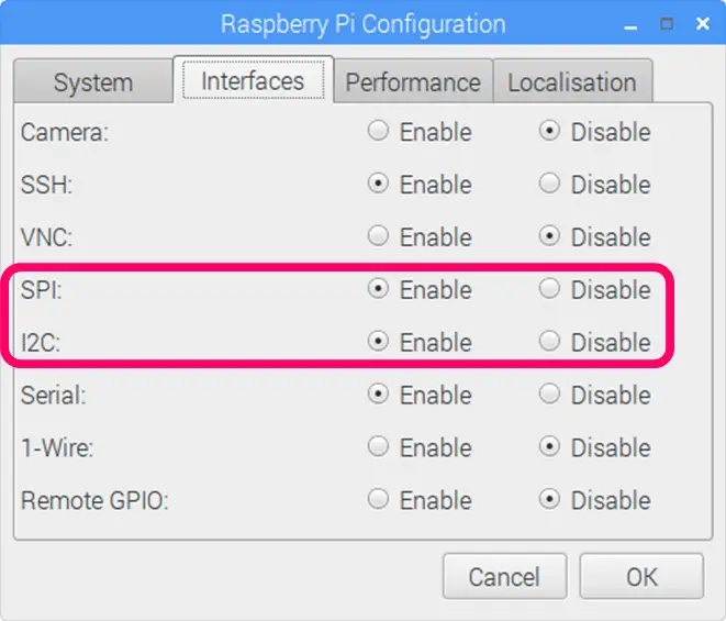
The only software requirement is to enable the SPI and I2C interfaces. From the Pi menu, click Preferences – Raspberry Pi Configuration. Click the Interfaces tab and enable the MCP3002’s SPI interface and the ADS1115’s I2C interface. If you are interested, I will have a more detailed tutorial on SPI and I2C communication protocols.
Fortunately, the latest version of Raspbian simplifies these operations by eliminating the need for superuser privileges to access the GPIO pins. Adafruit did build a python library for the MCP3008, an 8-channel version of the MCP3008.
However, during the testing, I found it was not fully compatible. So I wrote the following poll_sensor function. It reads the specified ADC channel and returns a 10-bit result.
The following program polls the sensor every 2 seconds and displays the voltage and 10-bit data values to the housing. Two-color LEDs are also used to indicate the presence of water (green: none, yellow: some water, red: water).
from time import sleep
import RPi.GPIO as GPIO
import spidev
spi = spidev.SpiDev()
spi.open(0, 0)
spi.max_speed_hz = 250000
GPIO.setmode(GPIO.BCM)
GPIO.setup(14, GPIO.OUT)
GPIO.setup(15, GPIO.OUT)
def poll_sensor(channel):
“””Poll MCP3002 ADC
Args:
channel (int): ADC channel 0 or 1
Returns:
int: 10 bit value relating voltage 0 to 1023
“””
assert 0 <= channel <= 1, ‘ADC channel must be 0 or 1.’
First bit of cbyte is single=1 or diff=0.
Second bit is channel 0 or 1
if channel:
cbyte = 0b11000000
else:
cbyte = 0b10000000
Send (Start bit=1, cbyte=sgl/diff & odd/sign & MSBF = 0)
r = spi.xfer2([1, cbyte, 0])
10 bit value from returned bytes (bits 13-22):
XXXXXXXX, XXXX####, ######XX
return ((r[1] & 31) << 6) + (r[2] >> 2)
try:
while True:
channel = 0
channeldata = poll_sensor(channel)
voltage = round(((channeldata * 3300) / 1024), 0)
print(‘Voltage (mV): {}’.format(voltage))
print(‘Data : {}\n’.format(channeldata))
if voltage < 50:
Green
GPIO.output(14, GPIO.HIGH)
GPIO.output(15, GPIO.LOW)
elif voltage < 1800:
Yellow
GPIO.output(14, GPIO.HIGH)
GPIO.output(15, GPIO.HIGH)
else:
Red
GPIO.output(14, GPIO.LOW)
GPIO.output(15, GPIO.HIGH)
sleep(2)
finally: # run on exit
spi.close() # clean up
GPIO.cleanup()
print “\n All cleaned up.”
This is the breadboard water detection circuit.
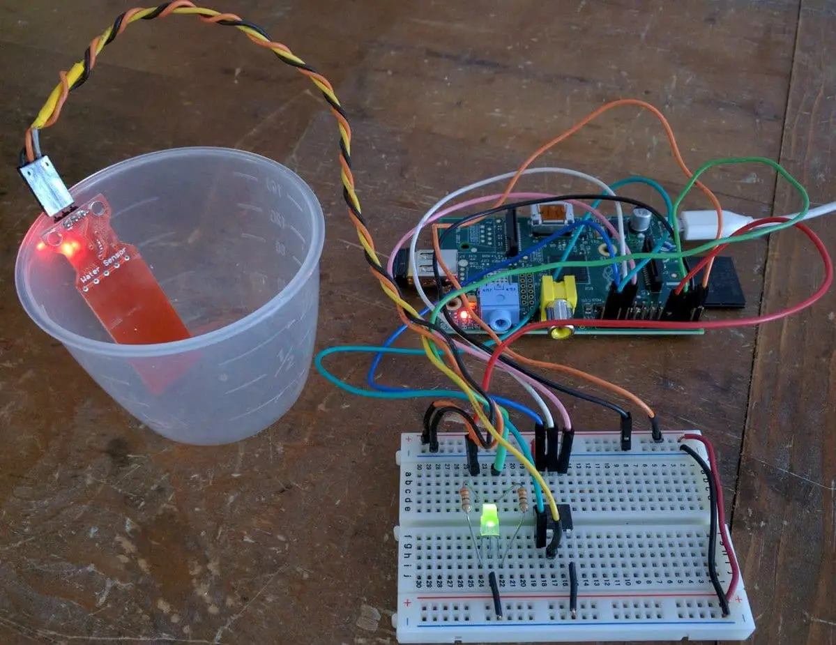
I found that the water level sensor is not very accurate, but the detection of water is good. Water pressure sensors can also be used to measure the water level by monitoring the pressure at the bottom of the tank.
I am using a 200 PSI sensor to measure my home pipeline pressure, which can be up to 180 PSI. For the water level, you can use a much lower pressure sensor.
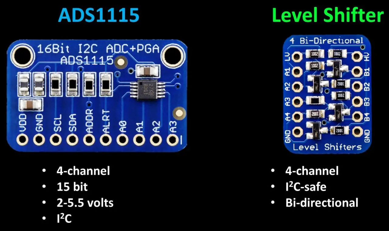
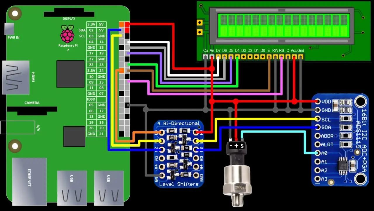
For the pressure sensor connection, I will use the ADS1115 breakout board. This is a 4-channel I2C ADC. Its 15-bit resolution is more accurate than the 10-bit MCP3002.
It supports power from 2 to 5.5 volts and works well because the pressure sensor is running at 5 volts. I will also use the Adafruit I2C Safety Level Shifter between the 3.3V Pi and the ADS1115 at 5V.
In theory, I could connect to the ADS1115 without an I2C level shifter, but that would go beyond the specs and I might have to remove the pull-up resistor on the interrupt board. So, I think it’s safer to use cheap gearshift. By exposing the GPIO pin to a voltage of 5 V, Pi may be damaged.
The ADS1115 connects to Pi using I2C lines SDA (GPIO2) and SCL (GPIO3). The Pi’s SDA and SCL are connected to the low side of the level shifters on ports A1 and A2.
The SDA and SCL of the ADS1115 are connected to the high-voltage side of the shifters of the respective ports B1 and B2. The shift register is located between the Pi and ADS1115 and moves the voltage appropriately to protect Pi and ensure reliability.
The LV (low voltage) pin on the shifter is connected to the 3.3 V pin on the Pi. The HV (high voltage) pin of shifter and the VDD of the ADS1115 are connected to the 5 V pin on the Pi. All three committees share one floor.
The pressure sensor plus pin becomes 5 volts, the negative pin becomes grounded. The “S” pin is connected to A0 on the ADS1115 ADC channel zero. LCD monitor for visual feedback. For more information on using the LCD monitor on the Pi, see my LCD monitor tutorial.
Adafruit provides a very handy python library for the ADS1115. The Adafruit-ads1x15 library can be easily installed using pip.
sudo pip install adafruit-ads1x15
Adafruit also provided a great python library for the LCDs I used on several projects. Now easier to install. Use pip again to install the Char LCD library.
sudo pip install adafruit-charlcd
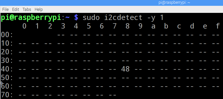
Next, use i2cdetect to ensure the wiring is OK and to obtain the hex address of the ADS1115. 1 parameter specifies bus 1. On older Pi, this may be zero.
sudo i2cdetect -y 1
The matrix shows that the ADS1115 is properly connected at hex address 0x48.
python code into the Adafruit_CharLCD library and instantiate and specify the GPIO pins and display size of the LCD. The Adafruit_ADS1x15 library is imported, and ADC is instantiated, specifying the hexadecimal address 0x48 from the i2cdetect tool and bus number 1.
Gain set to 2/3 for reading voltages up to 6.144V. If you are reading a lower voltage, Table 3 in the datasheet has a different gain value. Please note that no voltage higher than the VDD pin should be allowed to contact the ADC channel.
Since the voltage of the ADS1115 is 5 volts, the voltage on one of the ADC channels may exceed 5.3 volts. The main loop polls the sensor and displays the result on the LCD display.
from time import sleep
from Adafruit_CharLCD import Adafruit_CharLCD
lcd = Adafruit_CharLCD(rs=25, en=24, d4=23, d5=18, d6=15, d7=14,
cols=16, lines=2)
import Adafruit_ADS1x15
adc = Adafruit_ADS1x15.ADS1115(address=0x48, busnum=1)
Gain = 2/3 for reading voltages from 0 to 6.144V.
See table 3 in ADS1115 datasheet
GAIN = 2/3
Main loop.
while 1:
value = [0]
Read ADC channel 0
value[0] = adc.read_adc(0, gain=GAIN)
Ratio of 15 bit value to max volts determines volts
volts = value[0] / 32767.0 * 6.144
Tests shows linear relationship between psi & voltage:
psi = 50.0 * volts – 25.0
Bar conversion
bar = psi * 0.0689475729
lcd.clear()
lcd.message(“{0:0.3f}V [{1}]”.format(volts, value[0]))
lcd.message(“\n{0:0.0f} psi {1:0.1f} bar”.format(psi, bar))
sleep(1)
The voltage is calculated by dividing the 15-bit return value by 32,767,10-bit resolution and multiplying by the maximum gain voltage of 6.144. When I first tested the sensor, I determined that the relationship between PSI and voltage was linear and y = mx + b to determine the linear equation.
WebMath has a great online equation calculator that automatically solves a 2-point line equation. It provides a complete explanation of the answer and how to solve the equation. For this sensor, PSI = 50 x volts – 25. The voltage returned by insertion returns the PSI reading. The display shows voltage, data readings, PSI and BAR.


