


In this article, I’ll briefly describe how pulse oximetry works and how to understand the data from the MAX30100. The structure of this article will explain in each successive step why such filtering is applied and how it is calculated. The main implementation consists of two parts: reading pulses with only infrared LEDs and calculating SaO2 simultaneously with red and infrared diodes. At the end of the article, you should be able to understand the phases of the signal experience. These methods should work for any sensor, even your own or your own.
What is a pulse oximeter?
A pulse oximeter is basically an instrument that measures the pulse and oxygen saturation in the blood. Usually, this sensor consists of two LEDs that emit light: the red spectrum (650nm) and the other infrared spectrum (950nm). The sensor is placed on your finger or earlobe, and basically, the skin is not too thick, so both light frequencies penetrate the tissue easily. Once they have shined through your fingers, the absorption is measured by a photodiode. Depending on the amount of oxygen in your blood, the ratio of red and infrared absorbed will vary. From this ratio, you can “easily” calculate your hemoglobin oxygen content
A pulse oximeter is a device for monitoring heart rate and blood oxygen concentration. This equipment is especially important for those who need to monitor these parameters because of certain medical conditions, such as asthma or congestive heart failure.
Project idea
In the implementation of the pulse oximeter, we will use MAX30100 chip, integrated Arduino Uno and LCD keyboard shield. The chip serves as an integrated pulse oximeter and heart rate monitoring sensor solution. It should be noted that the MAX30100 is not an FDA-approved medical device and we are doing this for a small project of our bio-instrumentation class.
Our overall goal is to make a fingertip pulse oximeter:
- Modulate the light from the IR LED and the red LED
- Using the MAX30100 and Arduino
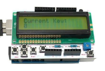
- Display heart rate or oxygen saturation on the LCD
- Allows the user to select the output to be displayed by pressing the button on the LCD
Collect Hardware to Build Project with Oximeter sensor using Arduino
Things you need:-
- Arduino Uno x1 (Buy Amazon)
- MAX30100 breakout board x1 (Buy Amazon)
- Jumper wires (Buy Amazon)
- welding wire (Buy Amazon)
- welding iron (Buy Amazon)
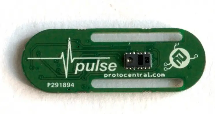
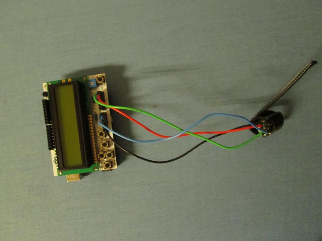
We got a copy of the MAX30100 relay board from ProtoCentral, which is ready to be inserted into the Velcro slot to wrap the device around your finger. We also have to solder the jumper to the drop-out board pin to connect it to the Arduino.
Project Idea
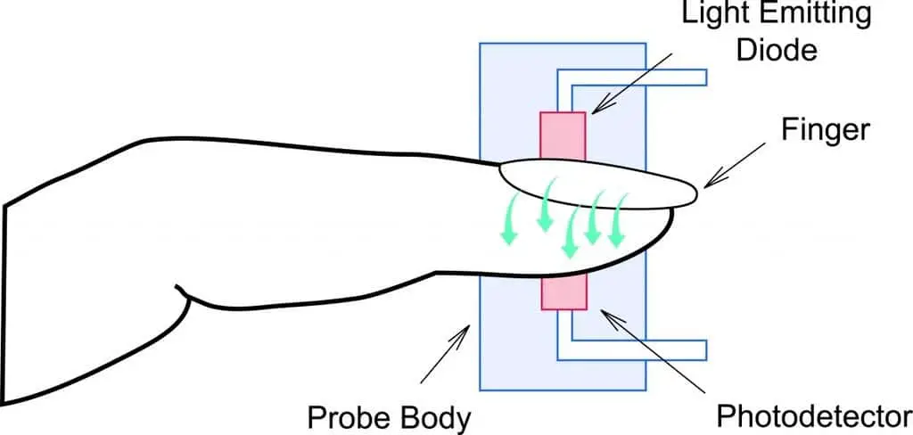
Pulse oximeters operate on the red and infrared light absorption properties of oxidized and deoxyhemoglobin. The oxygen concentration can be calculated by the ratio of the absorption of red and infrared light by hemoglobin. The heart rate is measured by changes in the blood volume of the entire finger and then quantified by the amount of light passing through the finger.
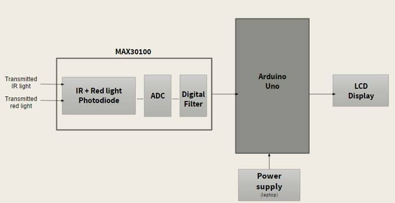
The MAX30100 chip integrates two LEDs: infrared and infrared (IR), a photodetector and low-noise signal processing to detect pulse oximetry and heart rate signals. Absorption data for IR and red light is stored in FIFO buffers up to 64 bytes. It provides two modes of operation; heart rate mode, heart rate, and oxygen saturation mode. In heart rate mode, only the infrared LED is on, while in dual mode both the infrared and red LEDs are on. It also has an integrated 60 Hz low-pass filter. Although it filters out power line noise, it does not account for environmental noise and fluctuations.
The red and infrared light is transmitted through the fingers and the integrated photodetector inside the chip senses the light absorption at two independent wavelengths. In this project, we also use the oxygen saturation and heart rate detection means, in order to simultaneously detect heart rate and oxygen saturation.
Wiring
Flow Chart
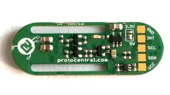
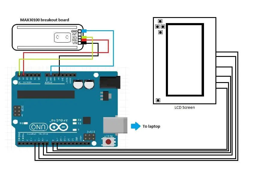
The MAX30100 is an I2C device, so the Wire library and Arduino interface are required by code. Physically, the MAX30100, in this case, the splice board, is connected to the Arduino via special pins that read data from the SCL and SDA lines (A4 and A5). SCL and SDL lines provide data signals and clock signals. Ground and Vin lines are connected to GND and 5V lines respectively.
The LCD keypad is connected to the Arduino via pins 4-8 so that we can provide a user-friendly display. We also use two buttons on the LCD keypad cover to select between two modes: heart rate monitor and oxygen concentration monitor.
Upload source code
Note: if you are beginner in Arduino then please have a look at my previous article “Beginner guide for Arduino”
#include <Arduino.h>
#include <math.h>
#include <Wire.h>
#include “MAX30100.h”
MAX30100*pulseOxymeter;
LiquidCrystal lcd(8,9,4,5,6,7)
int mode = 0;
void setup() {
Wire.begin();
lcd.begin(16,2);
lcd.print(“Up for SaO2”)
lcd.setCurson(0,2);
lcd.println(“Pulse oxymeter test!”)
pulseOxymeter = new MAX30100( DEFAULT_OPERATING_MODE, DEFAULT_SAMPLING_RATE, DEFAULT_LED_PULSE_WIDTH, DEFAULT_IR_LED_CURRENT, true, false);
pinMode(2, OUTPUT);
}
void loop() {
pulseoxymeter_t result = pulseOxymeter->update();
if ((analogRead(0)>130) && (analogRead(0)<160)) {
lcd.clear();
lcd.setCursor(0,0);
lcd.print( “SaO2: ” );
mode = 1;
} else if ((analogRead(0)>130) && (analogRead(0)<160)) {
lcd.clear();
lcd.setCursor(0,0);
lcd.print( “BPM: ” );
mode = 2;
if (result.pulseDetected == true)
{
if (mode == 1) {
lcd.clear();
lcd.setCursor(0,0);
lcd.print( “SaO2: “);
lcd.print( result.SaO2 );
lcd.print( “%” );
} else if (mode == 2) {
lcd.clear();
lcd.setCursor(0,0);
lcd.print( “BPM: “);
lcd.print(result.heartBPM);
}
}
delay(10);
digitalWrite( 2, !digitalRead(2) );
}
NOTE If you face any problem regarding this project then please write comment below
Visit similar projects tutorials on Raspberry Pi and Arduino
How to Build your own Super Computer with Raspberry Pi 3 Cluster
Build Super Computer with 5$ Raspberry pi zero using Cluster HAT
How to make a Raspberry Pi bitcoin mining rig


